How to: Temp/Humidity Sensor and Relay Device using EzloPi

Part 1:

I’ve been hearing about these “EzloPi” devices and decided to have a go at building one myself.

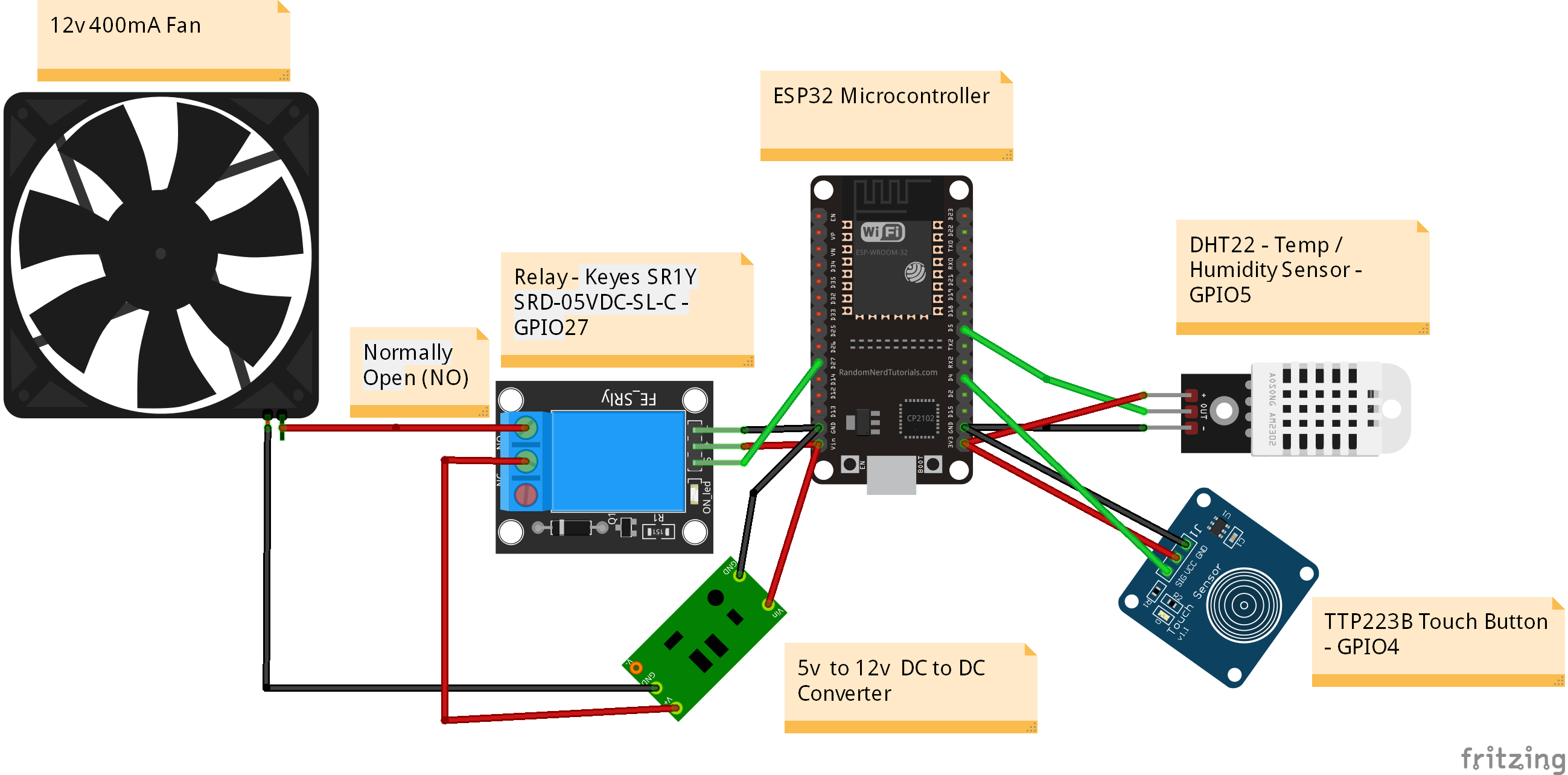
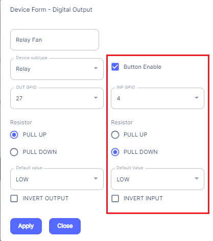
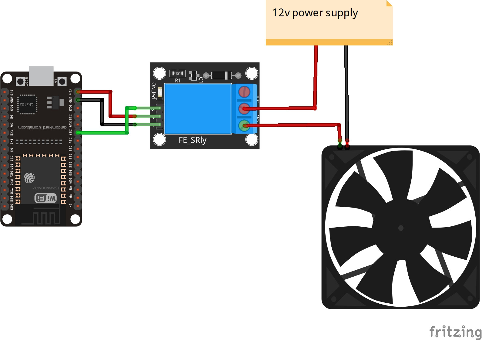
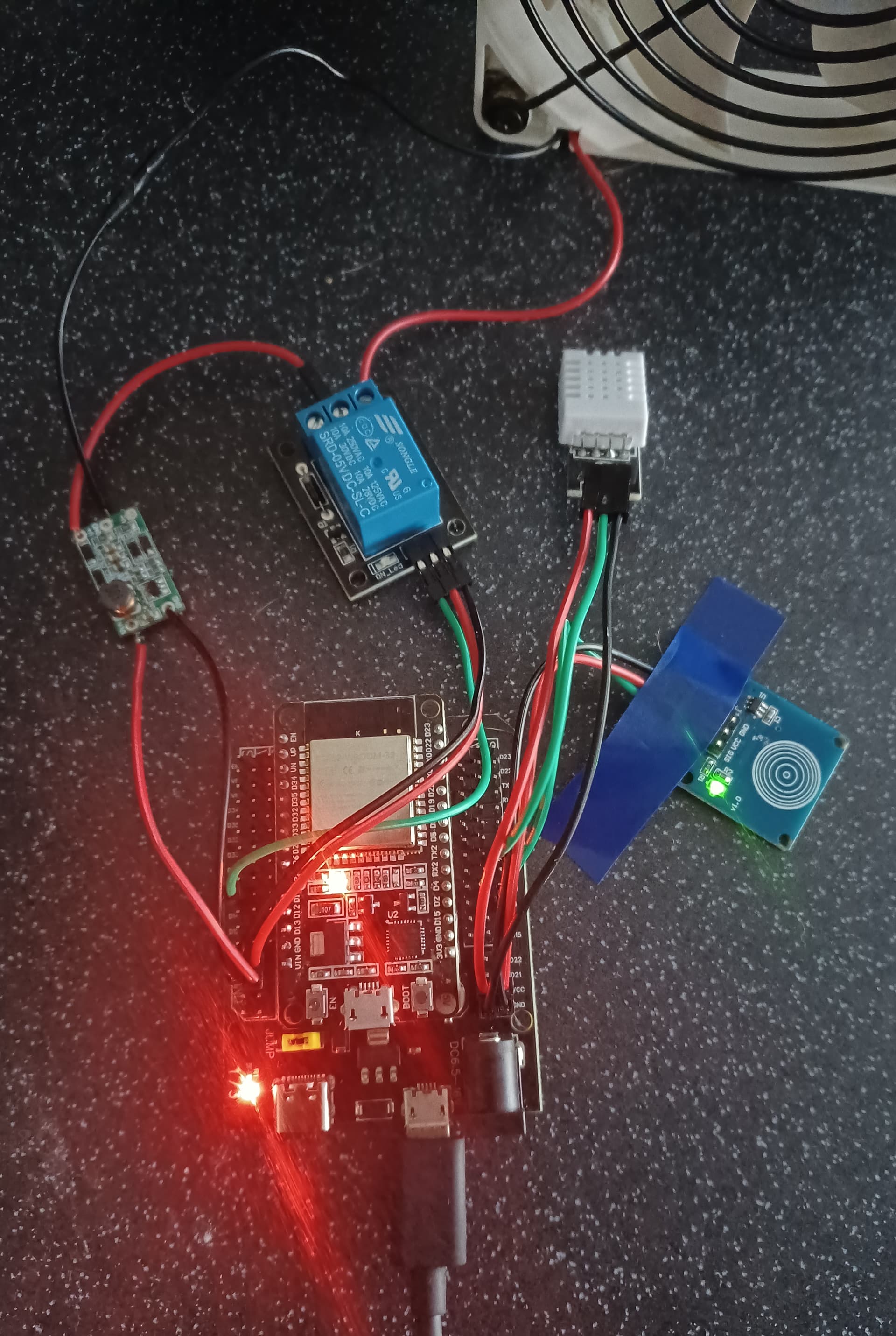
I wanted a Fan for the back of my router as its been getting hot in the cupboard. So thought I could use a Relay for turning the fan on and off and also add a temperature sensor while I am at it. I also added a touch button for local control.

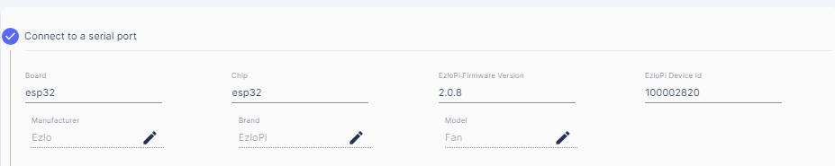
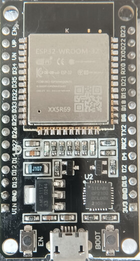
I got an ESP32 board:

ESP32-WROOM-32

Chip Information -
XX5R69
Silabs CP2102
DCL00X
2108+

Looking on the EzloPi website, there are some tutorials here, so I had a look at those and picked a Relay and a Temp/Humidity Sensor and also a Touch button.

I bought these items off Aliexpress.

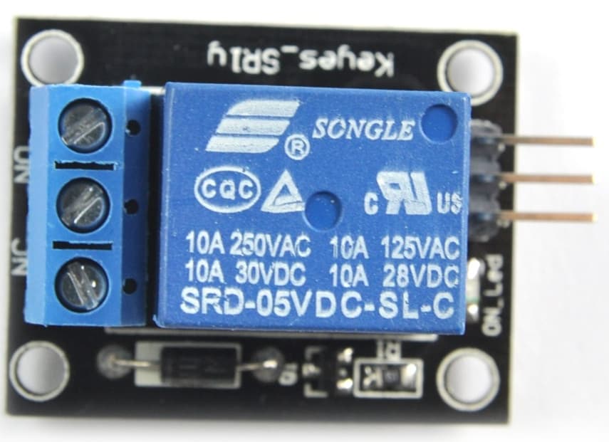
Relay - Keyes SR1Y SRD-05VDC-SL-C

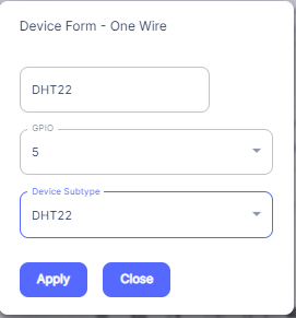
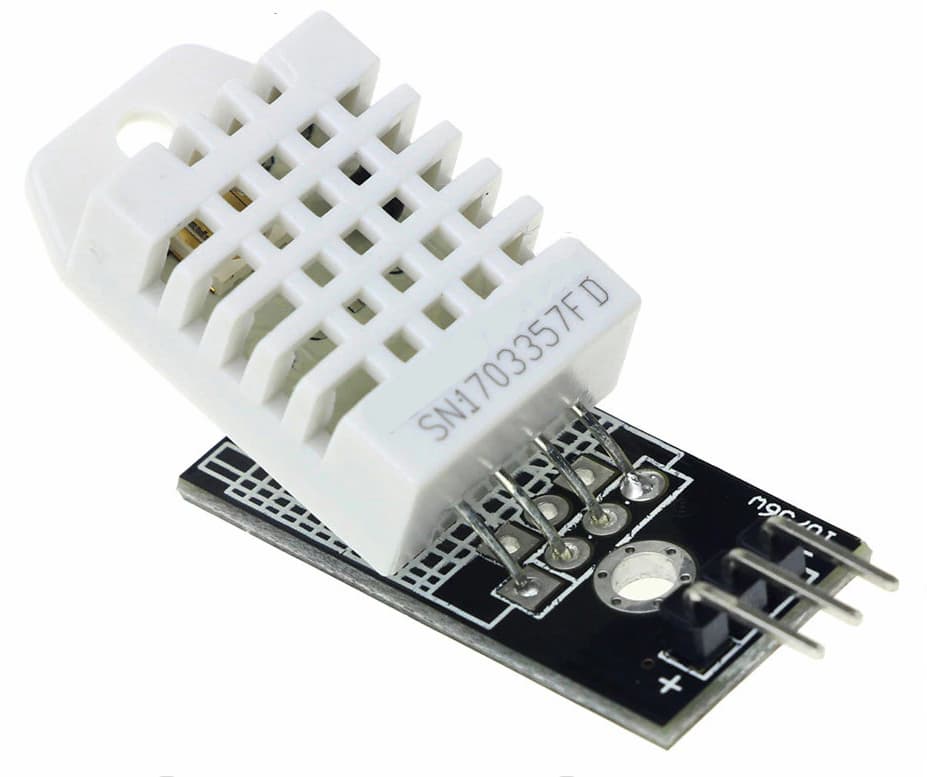
Temp / Humidity Sensor - DHT22

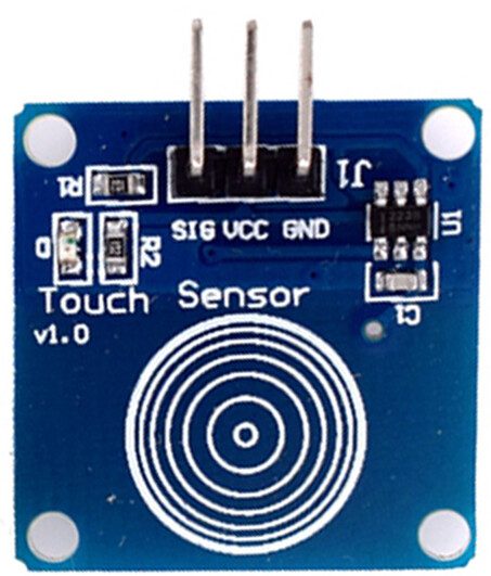
Touch Button - TTP223B

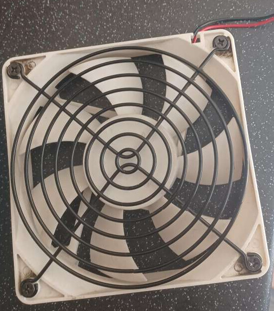
I pulled a 12V 400mA Fan out of an old computer PSU I had laying around.

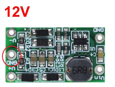
So this meant I also needed a 5V to 12V DC to DC step up converter.

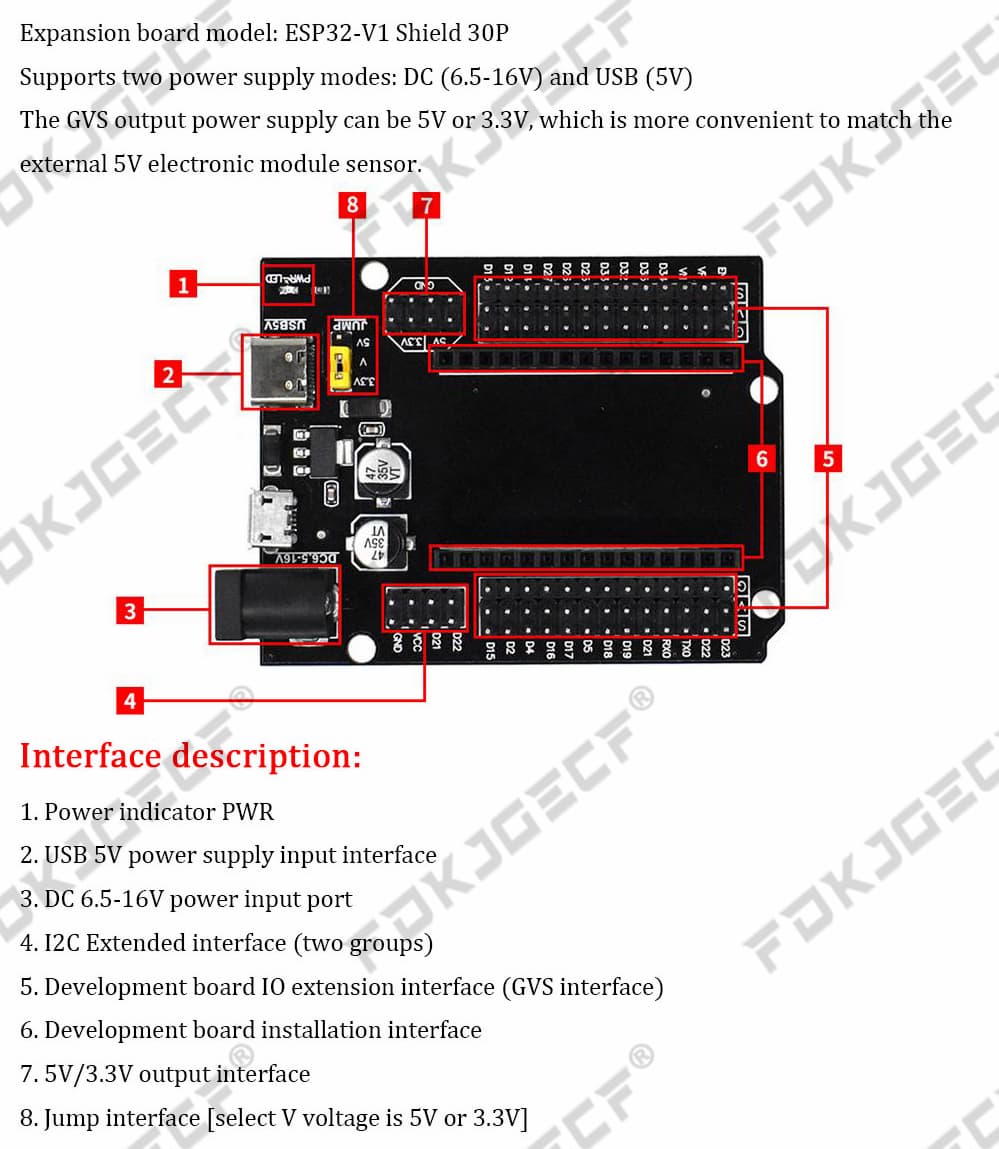
I also bought this ESP32 expansion board which made it easier for connecting more things to the 5v and 3.3v / GND output of the ESP32 board. Using number 7 and 4 in the picture below.

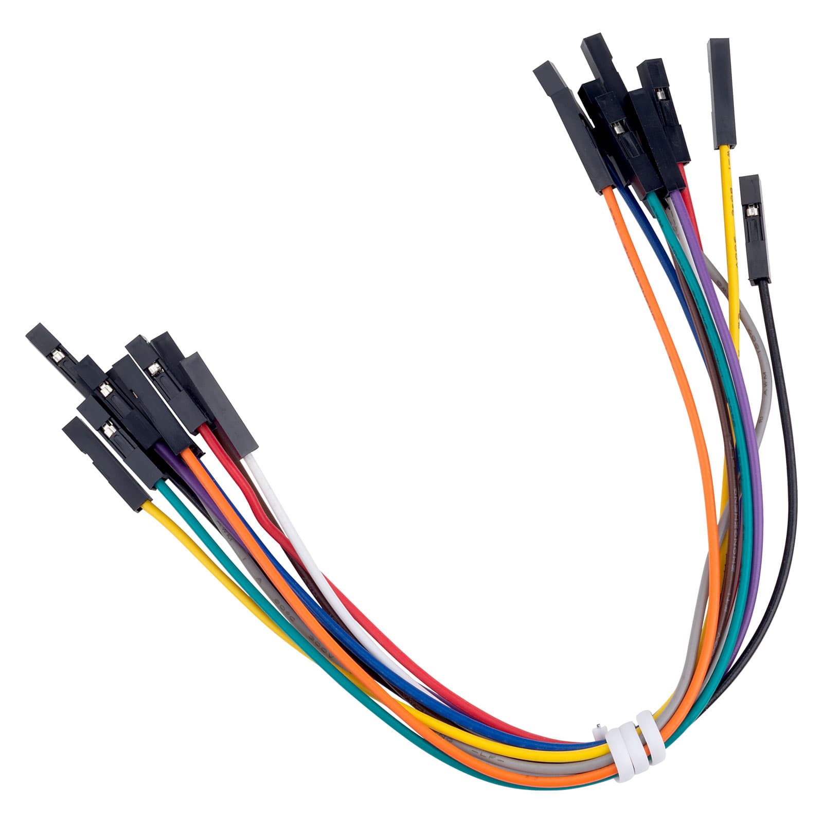
And some female to female dupont cables.
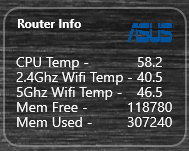
Bench testing -

There is a short video of the relay / fan in action here:

EzloPi-Relay-Temp-Humidity.mp4

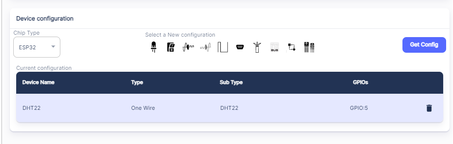
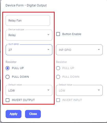
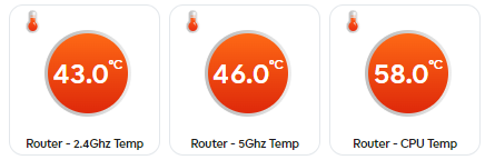
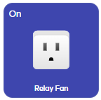
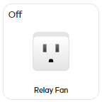
Relay button / dashboard tile in Ezlogic web UI, pressing this ON / OFF controls the fan etc.

image
image

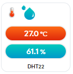
Temp / Humidity dashboard tile:

image

Note - If you do not see the tiles on your dashboard, you might need to go to the Settings - Controllers area in the Ezlogic Web UI and add the EzloPi “Controller” into your existing Controller group.

There was some soldering involved, which I am not great at, but managed to do it, for the DC/DC step up converter as I had to solder wires on to it.

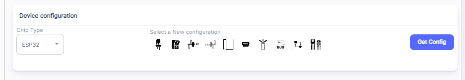
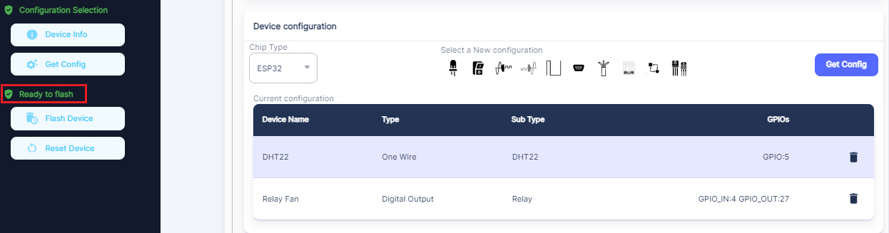
In Part 2 - I will try and draw a wiring diagram and look at the EzloPi Web Flasher site and how I programmed the ESP32 board with the correct settings / options etc.

4 Likes

Part 2:

This is my wiring diagram. I did not show the ESP32 Expansion Board I used, as I could not find a part for it in the sketch diagram app I used. But it should be fairly clear where all the wires go.

EzloPi Web Flasher Site:

If you are a complete novice like myself don’t worry flashing the “EzloPi” firmware and configuration to the ESP Microcontroller board is very easy indeed.

First I downloaded the “Universal” Windows drivers from this page here this enabled my Windows 10 PC to communicate with the ESP board on a USB “Com” port.

Then I went to the EzloPi Web Flasher Site here. I think I just signed in with my regular Vera account user name and password, if not just register for a new account login etc.

Once your ESP board is connected to your PC via a USB data cable you can click “Connect Device” on the menu.

image

Select the serial port and click the Connect button.

image

It should then go Green and say Connected

image

On the first section in the “Manufacturer” “Brand” and “Model” fields you can enter any descriptive text you wish.

Note the “EzloPi Device ID” is auto generated and will be the serial number of this EzloPi “Controller” that you will see on your account etc.

On the next section enter your 2.4Ghz WIFI SSID name and password, this is the WIFI that the ESP board will be connected too.

On the next section “Device Configuration” this is where you tell the system what sensors you have connected and on which GPIO pins etc.

I just looked at the EzloPi Tutorial web pages for the sensors, I kind of just followed what they did in their user guides etc.

For the DHT22 Temp and Humidity Sensor I selected a “One Wire” device and I used GPIO5 think they used 4 in their guide but it does not matter.

The first field on this dialogue box is the name that will appear in your Ezlogic web UI and mobile apps, so call it what you want. Select the desired GPIO pin and select the “Device Subtype” as DHT22 and click apply.

image

That section will then look like this:

Next I added my Relay device. I looked at this tutorial page that also used that same relay device so I could see how I should add the device etc.

So I needed to select the “Digial Output” option. The name “Relay Fan” is again what you will see in your Ezlogic web UI and mobile apps. I selected “Relay” from the “Device Subtype” and selected GPIO Pin 27.

image

Now as I also wanted the touch button to control the relay ON / OFF locally as well, I had to do an extra step here.

Tick the “Button Enable”. I then select GPIO Pin 4 as that is the pin I connected my touch buttons Signal wire too etc. And I selected “Pull Down” as that is what they did in their Touch Button tutorial page here. Then click “Apply”.

image

The “Device Configuration” section then looked like this and on the left hand menu it says “Ready to Flash”.

If you press the “Flash Device” button it will then ask you to press and release the “Boot” button on the ESP microcontroller board. Be patient here and wait till it says flash is successful. It may take some time so just wait.

That’s it you have successfully flashed your first EzloPi device !

I have never used ESP microcontrollers or Arduino or anything of this nature before. So I am a complete novice. However with the EzloPi Web Flasher site you only need to know which device / sensor types to select and what GPIO pins you connected them too that’s it, easy-peasy.

Optional: I also set a static LAN IP address for the ESP32 microcontroller on my Asus Router, but you can just leave it obtaining a DHCP pool address if you wish.

Next I will cover how the EzloPi “Controller” appears in your Ezlogic web UI and mobile apps.

1 Like

Reserved for other future stuff !

Being able to “Automate” anything you want, without writing a single line of code is amazing!

2 Likes

Yes it is! @Melih. When I first heard about these “EzloPi” devices, I thought it probably sounded too complex and too difficult for me to do. As I had never used ESP or other microcontrollers before.

I am very technical, but I am not a developer or coder and have never claimed to be… Just a “power” user…

However I am glad I gave it some time and a try. As any user could do this.

As before I would only ever purchase expensive Z-Wave devices, I knew would work with my Vera or Ezlo controllers.

But now I see I can easily create my “own” devices integrated into the Vera / Ezlo eco system, that I could never even do or even buy as “Z-Wave” devices.

I have also done a soil moisture sensor device for my daughter, who is currently into having plants, to notify her when to water them etc.

EzloPi now opens up a whole different world of none Z-Wave / Zigbee sensors into our Home Automation world…

1 Like

Indeed, it opens up a way to create smart devices for creative minds without writing a single line of code!

I was also pleasantly surprised with the stability of IP devices on WiFi networks. I had visions of lost devices due to WiFi protocol idiosyncrasies. I have WiFi based devices that have run untouched for several months now. IP Templates need more functionality to be fully useful but EzloPi sidesteps this by being a self contained controller (controller-lite).

Still need peer network ability to run an EzloPi device as elements in a local meshbot (say running on an EzloPlus) but I am told this is coming. Cloud based meshbots have limitations.

Your DC/DC supply might be overloaded with a 12V 400mA fan. Might need to get a beefier one or operate at reduced speed.

I did wonder about that, the DC to DC chip says its 100mA. I will have a look for a different one then I guess.

This extra fan has dropped my Routers CPU temp by 9 degrees however !

Home Remote Dashboard app tile:

image

Ezlogic Dynamic Dashboard tiles:

image

Note:- I am currently using a MSR rule to get the temps off my router via SSH commands.

The other option would be to use an external plug-in 12V power supply adapter rather than a DC to DC converter chip and the ESP boards 5v power output.

1 Like

@curiousB The DC to DC converter I used had this GND port on the output side and I had to use that port in my wiring.

image

Looking on Aliexpress the others I have seen don’t have this middle GND port they just have V+ and V- outputs.

can you pls expand on this so that we can provide what you need.

and this pls.

what are the limitations you see that we should have as a priority.

I am trying to create a task list for the dev team from your feedback.
Thank you!

I’m sure CuriousB will answer, but Osman was already discussing this with him.

It might be the fan draws less than 400mA @ 12VDC → 4.8 Watts

You can measure fan current by putting ammeter in series with the fan and see what typical draw is. If 100mA or less you are fine as is.

Also a nit, but you might be better to switch the input side of the DC/DC converter so it only runs when the fan runs.

Blockquote melihLeader

(How to: - My first EzloPi Temp/Humidity Sensor and Relay Device - #12 by melih)

can you pls expand on this so that we can provide what you need.

I have done this before as CW notes in my other post but in summary;

1. many IP Template device types are placeholders for functionality to come. In fact only a couple types of devices can be used today.
2. No polling scheme for binary devices which may change state locally and then be out of sync with the master (Ezlo Plus.
3. Ideally an “instant function” like exists in ZWave, such that IP Devices can asynchronously notify the host of a state change without being polled (this would be IP devices nirvana)
4. Ability to parse multiple portions of a single response from a complex IP device instead and pass values upwards or stuff into variable for later use in meshbots.
5. Maybe a “how to guide” on parseing values usig pattern in the IP Template. It kind of cryptic
6. Some variables should be configurable in the device instance instead of (or in addition to) the IP Template instance. That way an IP Template can be used across more deivce types.
7. Once a device is spawned off of an IP Template and then the IP Template gets modifies that device becomes a rogue device with no parent template.

and this pls.

This relates to EzloPi being a peer controller to EzloPlus when it is typically just a device and not in fact a controller. At best a “controller-lite”. The problem is local meshbots on the same LAN cannot operate together except with cloud meshbots and those are prone to issues from network delays and outages. Lots of posts here on why local meshbots are preferred to cloud meshbots for certain functionality. There needs to be a way an EzloPlus controller can have a meshbot that operates with same LAN EzloPis

what are the limitations you see that we should have as a priority.

I am trying to create a task list for the dev team from your feedback.
Thank you!

1 Like

Yeah would be nice if you could create a Local Meshbot on your Ezlo Plus controller and also include an EzloPi device off the EzloPi “controller” as well.

Only way currently to have a single Meshbot with devices off different controllers, is to use a Cloud Meshbot. And those are lacking in functionality when compared to Local Meshbots.

OK thanks, good idea, I will try this.

Hi @curiousB

Here is the latest status on your requests:

  • DEV COMPLETE - Add polling for switch and power capabilities
  • DEV COMPLETE - Add motion sensor capability
  • DEV COMPLETE - use door/window and motion sensors capability in sensor device types.
  • DEV COMPLETE - set MQTT topics instead of HTTP URIs to send device commands, get data via mqtt messages ( this can be done in parallel if we can),
    • IN PROGRESS - stop polling after the device is not reachable for some time. Later I want to restart polling / or check manually if the device is reachable

QUEUE

    1. modify template parameters via device settings
    1. test HTTP requests while creating the template and see the response on the page directly.
    1. Ideally an “instant function” like exists in ZWave, such that IP Devices can asynchronously notify the host of a state change without being polled (this would be IP devices nirvana)
    • Maybe MQTT can correspond to this ?
    1. Ability to parse multiple portions of a single response from a complex IP device instead and pass values upwards or stuff into variable for later use in meshbots.
    1. Maybe a “how to guide” on parsing values using pattern in the IP Template. It kind of cryptic
    1. Once a device is spawned off of an IP Template and then the IP Template gets modifies that device becomes a rogue device with no parent template.
    • This should not be a problem when its parameters could be configured by settings.
    1. [Local Meshbot with multi Controller] This relates to EzloPi being a peer controller to EzloPlus when it is typically just a device and not in fact a controller. At best a “controller-lite”. The problem is local meshbots on the same LAN cannot operate together except with cloud meshbots and those are prone to issues from network delays and outages. Lots of posts here on why local meshbots are preferred to cloud meshbots for certain functionality. There needs to be a way an EzloPlus controller can have a meshbot that operates with same LAN EzloPis

For these dev complete ones, I need some more time to display them on UI. then We will directly give it to you for testing .

Thanks for your patience and interest.

3 Likes

I ditched using the 5v to 12V DC converter chip in this application and have now wired it up with an external 12v 2A power supply for the fan.

It was too unstable using the converter chip and the relay would often turn off again just after being turned on.

Although the DC to DC converter chip would probably work OK for other applications, if you weren’t overloading it like I was presumably doing.

1 Like

Whats the next project @cw-kid ? :slight_smile: