Scenario:
I have a Pentair IntelliCenter providing 120V to a 120W 12VDC Transformer through the Included Relay in the IntelliCenter for on off functionality of 12VDC yard lighting. I’d like to further control some of the lighting to not necessarily be on when the other lights are on. I have two FortrezZ MiMO2 + devices not currently in use. Interestingly enough www.fortrezz.com redirects to the Ezlo Website. I also have a MIMOLite not in use currently. I’d like to use the LVDC input on one these powered by the 12VDC coming from the transformer above and then use the output relay(s) to further be able to turn on and off certain lights.
Additionally, I may just bypass the relay in the IntelliCenter all together and just power these with 12VDC off the transformer to control all yard lighting with my old Vera Plus. Is this possible or are these relays only pulse relays?
I Cannot seem to find too much documentation and Lord knows where the documentation that came with these relays has gone. Any help or guidance would be much appreciated.
Are you sure 12VDC? Most landscape lighting is 12VAC.
Due to lower voltage, currents are higher so any relay needs to be able to handle that current level. There are a few dry contact zwave devices on the market. Depending how you segment the load lighting they may be able to handle the switching role directly but failing that they can be the control signal to a beefier relay.
I see Mimo output 1is rated 10A and 120W so it can switch directly some of your load. Might be pushing it switching entire load.
I’m using Dekor Lighting which is DC. I’m also using RV LED lights in some locations. Also, several landscapin light options on Amazon are DC. So the MIMO will work up to 120 Watts load but what commands to use?
The mimo will work for the lesser of 120W or 10A current. You have to watch inrush current as well but for low voltage lighting that probably isn’t a big issue ( it is an issue for line powered led lighting).
As for commands just pair it to your system hd it should appear as an one off switch(s) which you can control from the interface or in mesh bots/scenes.
I already have the MIMO 2+ paired to my Vera Plus but set them up for momentary pulse to turn on and off a VS Pool Pump I no longer use and hid the other commands. I suppose I should just unpair them and reset them and start over but IIR the command set for these was quite a pain in MiOS unless something has been updated.
All that said I’m going to control 16 lights with these specs so it looks doable at a total of 48 Watts plus line losses:
Voltage: 12Volt DC
Wattage: 3.0W
Current draw: 165mA
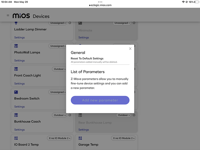
You might be able to reconfigure the mimo be setting new parameter values via the interface.
Sounds like no problem on load current, relay contacts should be fine.
Hi @Sammy2,
Since you’re using a Vera, configuring a MIMO from the Vera interface is relatively straightforward. The MIMO’s outputs REL1 and REL2 can in fact be used as normally open dry contact relays bypassing the latch.
- From the Dashboard click ‘DEVICES’ to see a full list of installed devices
- Click the ’ > ’ icon on the device you wish to configure.
NOTE: For devices that present as multiple icons in the UI (for example multi-sensors) you should choose the ‘parent’ device

- Click ‘DEVICE OPTIONS’ and then click the ‘Add configuration settings’ button
- Enter the parameter and values you would like to set:
- Variable: enter the Parameter Number (in this case either 1 or 2, or both if you wish to use both outputs)
- Data Size: this value will be shown in the device’s user manual - for parameters with a range of <255 select ‘1 byte dec’
- Desired Value: enter the value you would like this parameter set to
- Click the ‘SAVE CHANGES’ button to ensure you save your settings -
- Note: If you wish to see what value the parameter has (and not change it), select ‘Monitor Only’ in Data Size

- Parameters aren’t automatically transferred to the Z-Wave device, so it is best to force this to happen
- Click Back and then click ‘ADVANCED’
- Click ‘Configure Node Right Now’ - if it is a battery device ensure you wake it up.

- Go back to the device’s ‘DEVICE OPTIONS’ section
- You should now see that the correct value displays in the Current Value field - confirming that it has been transferred to the device correctly

For the MIMO see configuration parameters 1 and 2 in the files attached below. You might as well use the SIG1 and SIG2 analog inputs to map voltage readings on both to your desired momentary or fixed pulse. Simply set each parameter to 0 with 1 byte in size for non-momentary outputs.
User Manual MIMO2 .pdf (545.8 KB)
Tech Appendix MIMO2 .pdf (304.6 KB)
1 Like


