Part 2:
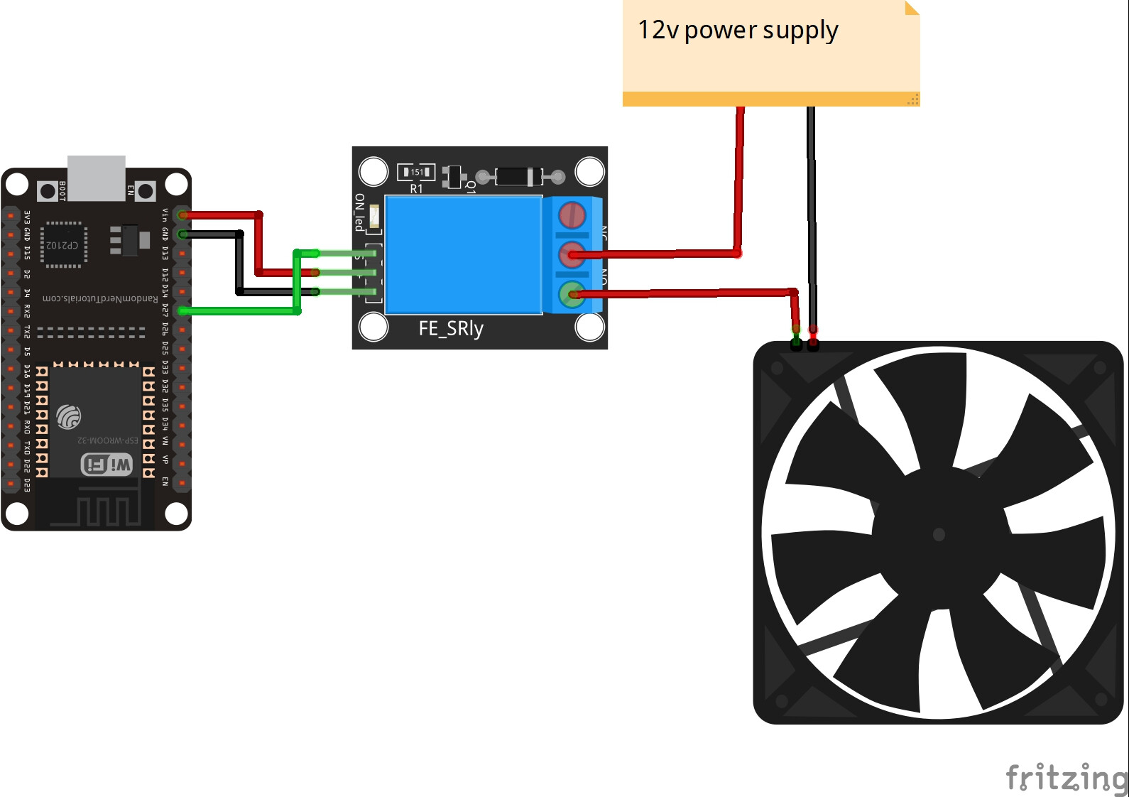
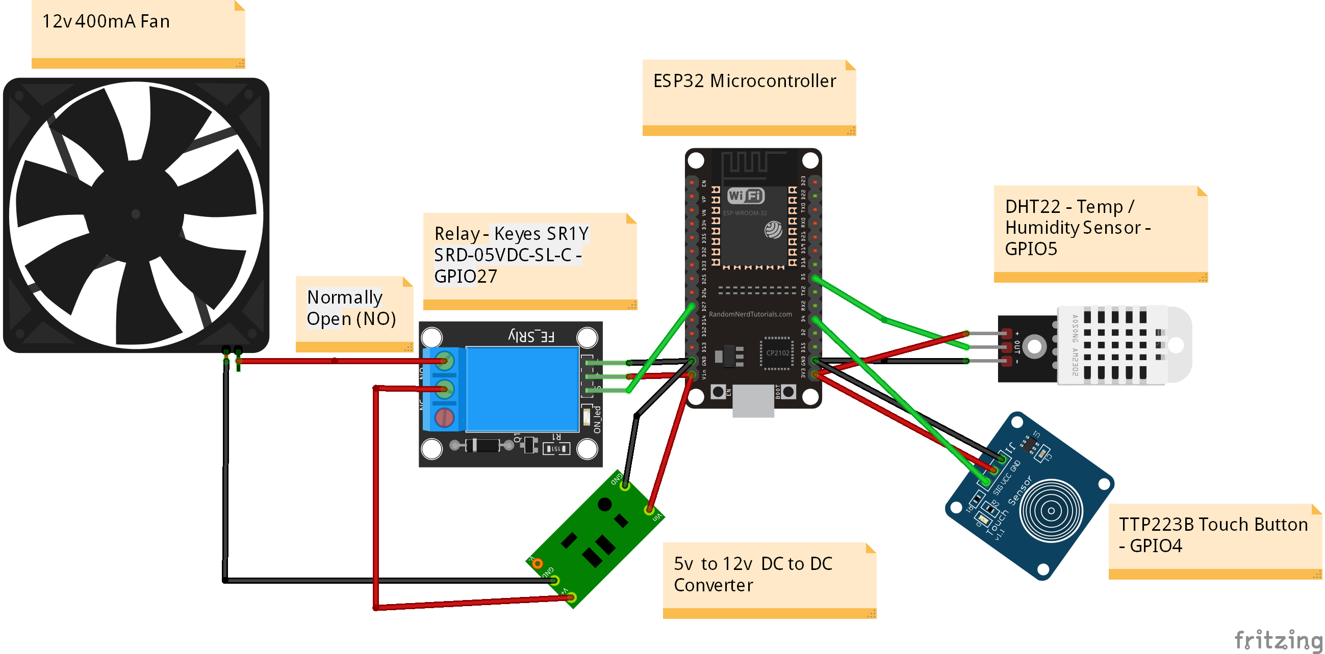
This is my wiring diagram. I did not show the ESP32 Expansion Board I used, as I could not find a part for it in the sketch diagram app I used. But it should be fairly clear where all the wires go.
EzloPi Web Flasher Site:
If you are a complete novice like myself don’t worry flashing the “EzloPi” firmware and configuration to the ESP Microcontroller board is very easy indeed.
First I downloaded the “Universal” Windows drivers from this page here this enabled my Windows 10 PC to communicate with the ESP board on a USB “Com” port.
Then I went to the EzloPi Web Flasher Site here. I think I just signed in with my regular Vera account user name and password, if not just register for a new account login etc.
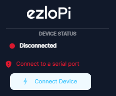
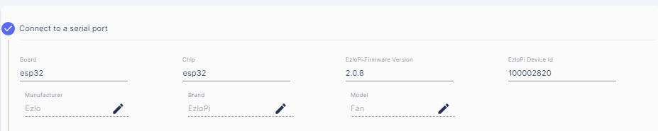
Once your ESP board is connected to your PC via a USB data cable you can click “Connect Device” on the menu.
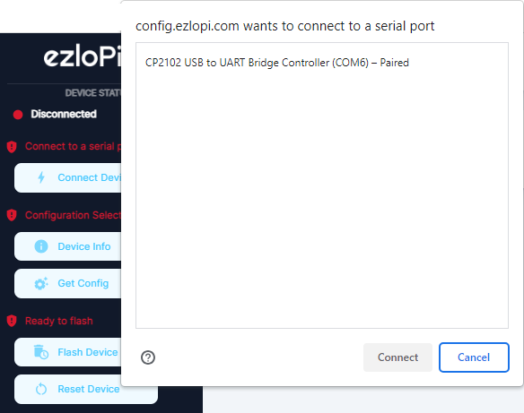
Select the serial port and click the Connect button.
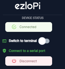
It should then go Green and say Connected
On the first section in the “Manufacturer” “Brand” and “Model” fields you can enter any descriptive text you wish.
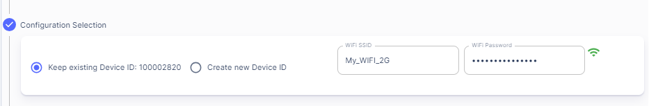
Note the “EzloPi Device ID” is auto generated and will be the serial number of this EzloPi “Controller” that you will see on your account etc.
On the next section enter your 2.4Ghz WIFI SSID name and password, this is the WIFI that the ESP board will be connected too.
On the next section “Device Configuration” this is where you tell the system what sensors you have connected and on which GPIO pins etc.
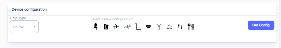
I just looked at the EzloPi Tutorial web pages for the sensors, I kind of just followed what they did in their user guides etc.
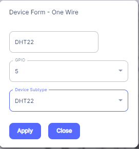
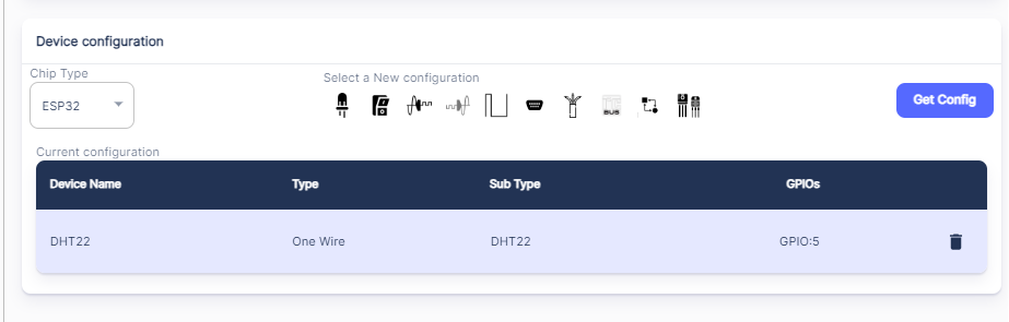
For the DHT22 Temp and Humidity Sensor I selected a “One Wire” device and I used GPIO5 think they used 4 in their guide but it does not matter.
The first field on this dialogue box is the name that will appear in your Ezlogic web UI and mobile apps, so call it what you want. Select the desired GPIO pin and select the “Device Subtype” as DHT22 and click apply.
That section will then look like this:
Next I added my Relay device. I looked at this tutorial page that also used that same relay device so I could see how I should add the device etc.
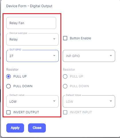
So I needed to select the “Digial Output” option. The name “Relay Fan” is again what you will see in your Ezlogic web UI and mobile apps. I selected “Relay” from the “Device Subtype” and selected GPIO Pin 27.
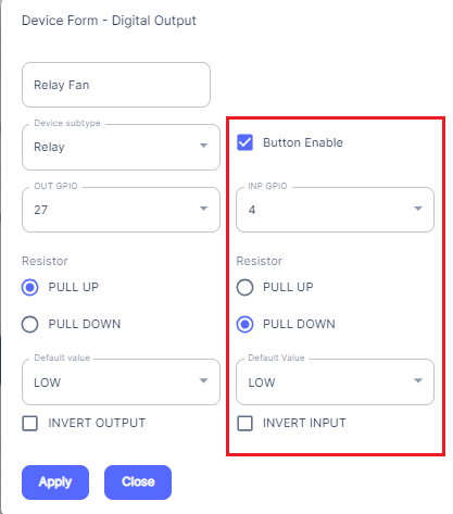
Now as I also wanted the touch button to control the relay ON / OFF locally as well, I had to do an extra step here.
Tick the “Button Enable”. I then select GPIO Pin 4 as that is the pin I connected my touch buttons Signal wire too etc. And I selected “Pull Down” as that is what they did in their Touch Button tutorial page here. Then click “Apply”.
The “Device Configuration” section then looked like this and on the left hand menu it says “Ready to Flash”.
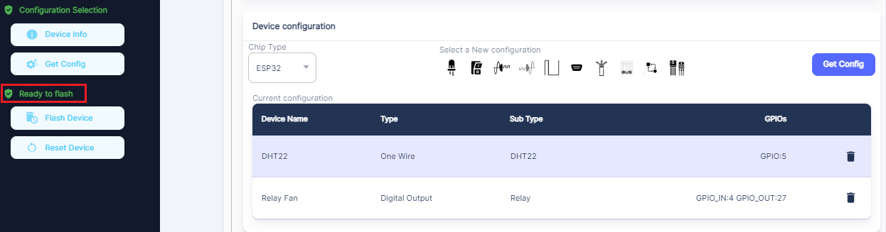
If you press the “Flash Device” button it will then ask you to press and release the “Boot” button on the ESP microcontroller board. Be patient here and wait till it says flash is successful. It may take some time so just wait.
That’s it you have successfully flashed your first EzloPi device !
I have never used ESP microcontrollers or Arduino or anything of this nature before. So I am a complete novice. However with the EzloPi Web Flasher site you only need to know which device / sensor types to select and what GPIO pins you connected them too that’s it, easy-peasy.
Optional: I also set a static LAN IP address for the ESP32 microcontroller on my Asus Router, but you can just leave it obtaining a DHCP pool address if you wish.
Next I will cover how the EzloPi “Controller” appears in your Ezlogic web UI and mobile apps.