Has anyone experimented with using a poe splitter to operate a vera edge in a location where power does not exist?
Would you expect to send 12V DC and connect to the Edge’s power connector? Or send 5V DC terminating with a USB A male inserted into its USB port?
Just curious, since I believe both approaches should work in theory, although it’s unclear if the latter method is sufficiently documented/tested to be considered reliable or wise.
12v DC to the power power port. I have used a Trendnet TPE-104GS for a similar application but would like some feedback to see what others have used.
1 Like
I would support connecting a 12 VCC output to Vera’s power input. Power through the USB port, which is intended to output +5 VDC , would be risky. It might work, but there’s no way to know what margins, if any, the power supply has.
Make sure the splitter is made by a recognized IT vendor and supports the IEEE 802.3af or IEEE 802.3at at standards. Many of the devices sold on the web are cheap junk that are not standards compliant and can damage your equipment. The IEEE standards require that the voltages are floating and not referenced to any common or exposed metal parts. Many of the inexpensive PoE devices don’t follow the standard and can cause damage to connected equipment that might have an earth ground connection.
1 Like
The older TPE-104GS i have is version 1.2R which looks like the max output is 1.2A. I would prefer to get a new one version 2.0 and it looks like they upped the amperage to 1.5A. I would think is the maximum draw, should it be ok to use it for this or do you think i need to find something closer to 1A?
Gigabit PoE Splitter - TRENDnet TPE-104GS (new one)
Gigabit PoE Splitter - TRENDnet TPE-104GS (discontinued)
here is another one i just found that i have and looks to be 802.3af/at compliant from Anivision (not sure on the reliability)
1 Like
The Vera supply provides 1A, and Vera itself draws somewhat less than that. Having a 1.5A supply won’t matter since the Vera isn’t drawing anywhere near that much. Many of the small splitters violate the standard as I mentioned in my earlier post. If your Vera is not connected to anything other than the Ethernet cable and the splitter output, that won’t matter. If you have a FLASH drive connected to the USB port, that’s OK since the drive floats along with Vera. If you connect something to the USB port that ends up connected to earth, some PoE splitters can cause problems. I have no experience with the ANVISON device.
1 Like
Interesting as I just happened to be on a big move of proliferating these splitters in my home and replacing all these AC/DC bricks and reduce the overall RF emission in the house. I already did the hue hub and all of my wifi cams which are now POE wired instead. The vera was going to be next and yes I can confirm that a simple 12V splitter will work just fine. Anvision is just a marketing brand, they are all from the same OEM in China.
1 Like
Doing some testing with these Anvision splitters i measured 12.4 volts with my multi meter at the power plug. My netgear gs516TP is reporting with the following measurements.
output 53.4 volt
output current 42 mA
output power 2.2 Watt
vera and poe splitter feels about the same. My single lock is working fine. Assumption that when i add a 2nd lock power consumption may go up slightly but over all no issues. ![]()
Dumb question here: If each powered device still needs its own supply, how does incorporating these PoE splitters reduce the overall number of wall bricks in your home?
(I’ve only deployed PoE twice – both times with cameras, who didn’t seem to mind me splicing the output of a single wall adapter to send 12V DC to all of them. Is that your approach??)
The benefits come from the following:
-
Space savings. These splitters are much smaller in general and are DC-DC converters which generate less heat and no RF. They also free up power outlet space.
-
If you intended to put a smart switch on them… now you don’t need to anymore as you can remotely power cycle them from the ethernet switch. I have a unifi network so… I can actually powercycle every port from openLuup/Home Assistant. No more dumb wifi or zigbee smart plugs which also occupy space and emit heat and RF.
-
The quality of these AC-DC converters also vary a lot as many oscillate quite a bit. You can test that by taking one of those cheap home depot pen shaped AC power detectors and go around and test the wire coming out of these DC converters… You will find out that many buzz the detectors. I tested a bunch of USB outlet for example and so far have only found the apple ones not to buzz. This means that the wire is also emitting some low level of RF since it is not designed to carry AC current and is not shielded. It emits enough to buzz the cheap Home depot/Sears sensor! Not sure what this does long term to your electronic’s reliability. And I won’t even talk about power efficiency… which also varies a lot and for which the loss is the source of heat.
-
You would basically move and concentrated all of these heat and emission to the POE switch which, well already was doing it so… And is a much better quality rectifier in my case than all these bricks.
2 Likes
who said anything about installing the controller in a house ![]()
1 Like
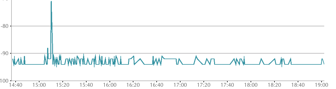
If you wonder what this does…
Impact from putting a splitter replacing the brick for a vera plus, which for me is connected to a uzb about 1m away (actual antenna location) and relaying the zwave serial signal to z-way in a VM measuring zwave background noise:
I did this at 16:15. My POE switch is only 40cm away but is shielded. The flat lines are generally below measurement limits. Note that I made quite a bit of changes to lower the noise level down from -75 ~ -80dB to where it was like removing unshielded usb hubs in the vicinity.
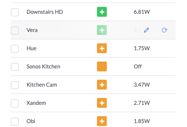
And added benefits: I can monitor power through Home Assistant/openLuup and turn power on and off for just the cost of the $5 splitter. No extra RF or power consumption/heat:
1 Like
hmmmm are you powering the vera with poe thru RJ45 ??? or what?
No it is powered by a splitter. Look at post #7. It is POE switch → CAT5E → Splitter =>Cat5E + power cable => Vera
aha… nice… didn’t know that the splitters existed… ![]()
At what distance does voltage drop start to become a problem? UTP cables are awfully small gauge!
The IEEE 802.3af standard mandates a minimum of 12.75 W delivered at 100 meters at a nominal 48 VDC . Many so-called PoE solutions are non-standard, YMMV.
3 Likes
Yes, generally it’s a 100m.
Adding shocking results on my production setup:
Note first that I have had 0 problem with zwave since moving it to z-way and donating my veras away. It is my OCD kicking in which got me to look at further optimizations:
Before swapping out the brick, I had ~5-6% CRC errors negating the success on reception bar and ~1-2% foreign neighbor impact. Now this:

A bit of explanation as I took the zniffer out to find out that everything that is not green on the graph are actually from my neighbor’s zwave network. Being further away and not relayed by any repeater, it tends to be seen by my network as either erroneous (top red bar) or if received correctly, dumped as “not my HomeID” (bottom red bar). This is done by the zwave chip firmware by the way and not reported unless the host controller firmware polls the data. Z-way just so happens to do it and have a display for it.
So what does this mean? Reducing the noise level around the zwave antenna lead it to be able to lower error rates by 50% and therefore recognizing more frames from my neighbor’s as foreign instead of saying they were erroneous.
For the first time, the percentages have flipped. What does it mean for my network? Potentially extended range and fewer hops as devices need fewer repeaters to reach the controller and vice versa. Less hops means less frames being repeated and a less chatty network which I am seeing at the top line where I get 0 “back off frames” and I see fewer frames being sent per equivalent period of time… and therefore an even more reliable zwave network with fewer frame collisions.
PS: Does this explain better why I am saying the multiple coordinated zwave controller makes no sense?