LDR digital module example
Requirements
a. Hardware Requirements
i. 1 ESP32 or ESP32S3 flashed with EzloPi firmware
ii. 1 LDR digital module
iii. 3 Jumper wires
b. Software Requirements
i. EzloPi desktop application
ii. Vera mobile application
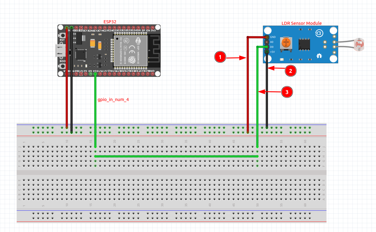
Circuit connection in ESP32
- LDR digital module VCC
- LDR digital module digital output
- LDR digital module GND
Adding LDR digital module from EzloPi desktop application
-
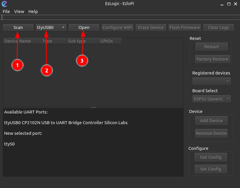
Connect the ESP32 to the computer and open the EzloPi desktop application.
-
Scan, select and open the serial port, connecting to the ESP32.
-
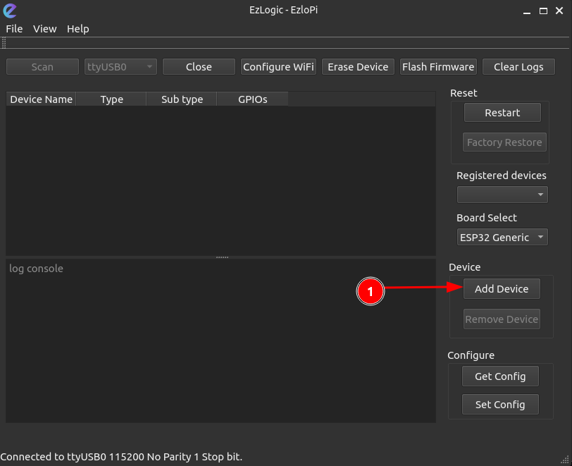
Click on the ‘Add Device’ button as shown below.
-
Select the “Digital Input” option from the dropdown menu.
-
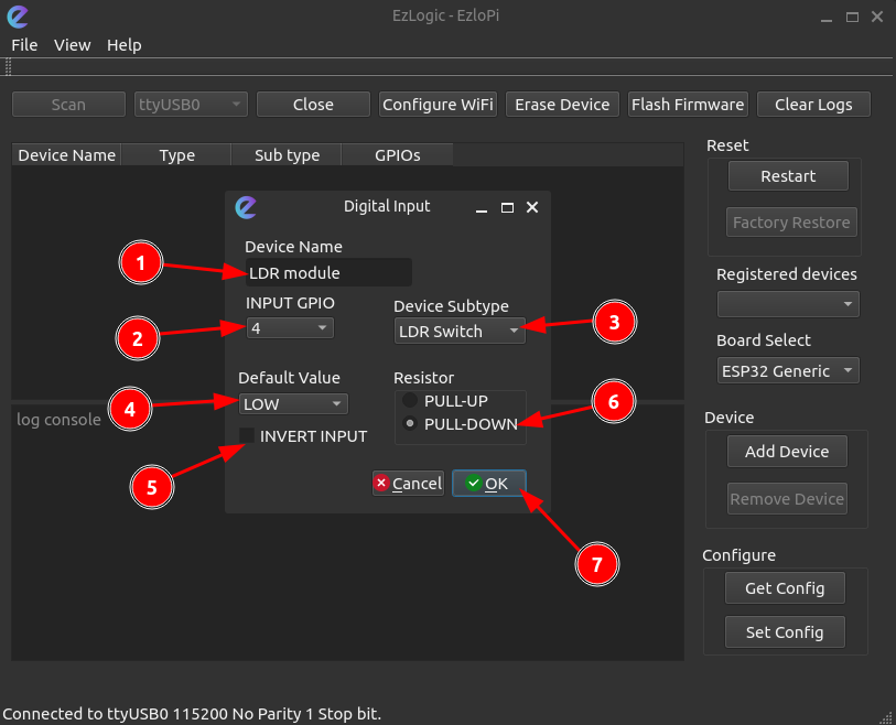
Configure the LDR digital module:
- Give it a name. (“LDR module” as an example)
- Select GPIO pin for digital input.
- Select the LDR switch from the dropdown menu.
- Select default input to “LOW”
- Click to checkbox if inverted input is required.
- Select the “PULL-DOWN” option.
- Then click “OK”.
-
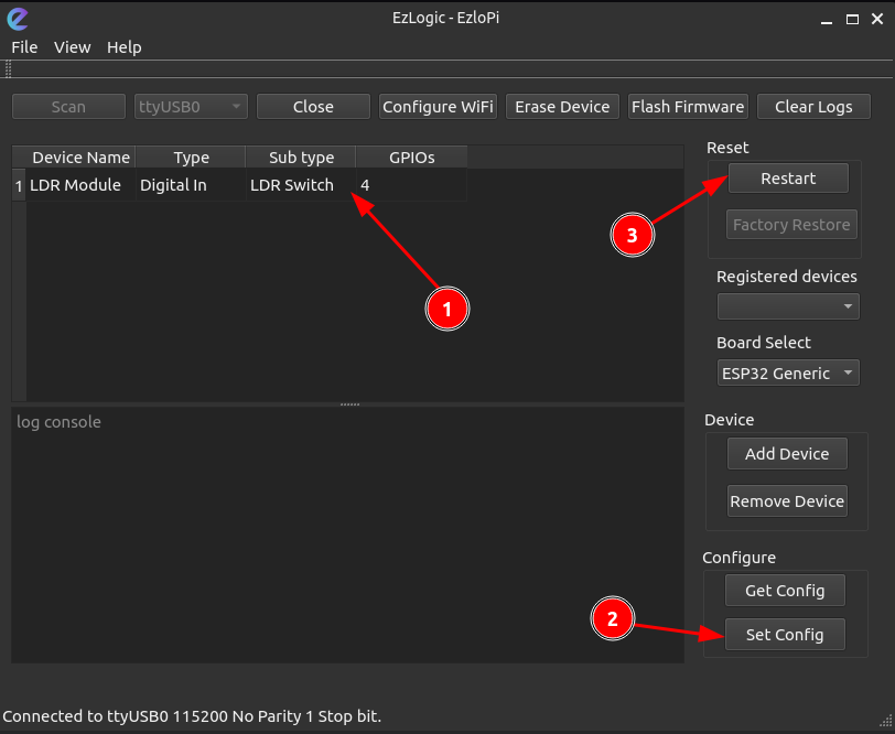
Device name, type, subtype and GPIOs are displayed in the screen; click on “set config” to burn the configurations to the ESP devices. Finally, reset the device by clicking on “Restart”.

LDR digital module in Vera Mobile Application
-
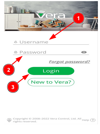
Login to the Vera app using username and password.
-
After login you should be able to see your controller online. The current controller shown has the serial 100004005. Make sure that after flashing the ezlopi firmware to the ESP32 device, you connect to the WiFi clicking Configure WiFi button in the UI.
-
After the device gets online, click on to the controller icon as shown as it appears online. It will take some time to reload and add the device configured from the configurator UI.
-
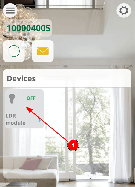
The LDR digital module connected will be shown in the ‘Devices’ panel.
-
Upon blocking the light to the LDR on the module, the GPIO value will change.
-
When the LDR is blocked from light falling into it, the GPIO pin will be activated i.e. switch in turned on. Which is indicated with a glowing lamp and ON state in the UI.
-
When the LDR is exposed to light, the GPIO pin will be deactivated i.e. switch is turned off. Which is indicated with a lamp being turned off and OFF state in the UI.