GE Z-Wave® Dimmer Switch (3-Way Kit)

meh. I despise the GE/Jasco 3-Way kits. I hate 'em! lol.

Don’t get me wrong, they’re great for new construction but they’re not designed to function properly with existing 3-Way circuitry. You’d basically either have to rewire your whole house or have an existing wiring setup that these switches support which is not the norm in construction.

The Main switch functions like a normal 3 Way switch should, however the secondary or auxiliary switch functions more like an on/off switch. Both require neutral and the main traveler (one traveler and not 2 like normal 3 way circuits have) has to be connected directly to the auxiliary switch in order for these kits to work properly.

I gave up trying to install the GE/Jasco kits in my house after I realized how they needed to be wired, and finally I just matched my existing 3-Way circuitry to a Z Wave Switch that would work according to how my existing 3 Way circuit is wired in my home.

Needless to say, I purchased the CA600’s which work fantastic and you can use them in a ‘normal’ 3 Way circuit.

If anyone needs help with 3 Way Circuits, please check out the below link…

[url=http://www.homeimprovementweb.com/information/how-to/three-way-switch.htm]http://www.homeimprovementweb.com/information/how-to/three-way-switch.htm[/url]

Can someone tell me if my wiring setup would be compatible with the GE 3 way kit. I attached the pictures below. The way I think it is wired is that the white neutral wire is configured to be the traveller. There is a leutron dimmer which has 2 red wires and one black. The black is wired to the hot on the next switch. One of the red wires is attached to the white wire and the other red wire is attached to a black wire. On the other switch, there is a white and a black attached to the upper terminals and a black (presume hot) to the common terminal. I am thinking the GE switch probably will not work with this setup. Thoughts?

From iflym3’s post above it looks like the CA600 may be a better option? If I use that switch as a dimmer I presume I can leave the regular secondary switch alone or does it require a special secondary switch like the GE does?

[quote=“iflym3, post:81, topic:167413”]meh. I despise the GE/Jasco 3-Way kits. I hate 'em! lol.

Don’t get me wrong, they’re great for new construction but they’re not designed to function properly with existing 3-Way circuitry. You’d basically either have to rewire your whole house or have an existing wiring setup that these switches support which is not the norm in construction.

The Main switch functions like a normal 3 Way switch should, however the secondary or auxiliary switch functions more like an on/off switch. Both require neutral and the main traveler (one traveler and not 2 like normal 3 way circuits have) has to be connected directly to the auxiliary switch in order for these kits to work properly.

I gave up trying to install the GE/Jasco kits in my house after I realized how they needed to be wired, and finally I just matched my existing 3-Way circuitry to a Z Wave Switch that would work according to how my existing 3 Way circuit is wired in my home.

Needless to say, I purchased the CA600’s which work fantastic and you can use them in a ‘normal’ 3 Way circuit.

If anyone needs help with 3 Way Circuits, please check out the below link…

[url=http://www.homeimprovementweb.com/information/how-to/three-way-switch.htm]http://www.homeimprovementweb.com/information/how-to/three-way-switch.htm[/url][/quote]

iflym3,

If your house has “neutrals” in each box, and is wired as modern houses are, the GE/JASCO switches work just fine.

If you have an older house, and it was wired “old school style” (without a neutral in each box, and other shortcuts), then stay away from the GE/Jasco’s for 3 way. They work fine in modern houses. I would say if your house is over 10-15 years old, it may be wired “old school” and you will probably have issues.

[quote=“tbever, post:82, topic:167413”]Can someone tell me if my wiring setup would be compatible with the GE 3 way kit. I attached the pictures below. The way I think it is wired is that the white neutral wire is configured to be the traveller. There is a leutron dimmer which has 2 red wires and one black. The black is wired to the hot on the next switch. One of the red wires is attached to the white wire and the other red wire is attached to a black wire. On the other switch, there is a white and a black attached to the upper terminals and a black (presume hot) to the common terminal. I am thinking the GE switch probably will not work with this setup. Thoughts?

From iflym3’s post above it looks like the CA600 may be a better option? If I use that switch as a dimmer I presume I can leave the regular secondary switch alone or does it require a special secondary switch like the GE does?[/quote]

You definately do not want to use a neutral as a traveller. Big no-no. However, it may be that the original installer may have used a white wire as one of the travellers. Unless the installer marked the white traveller wire appropriately (usually by using black electrical tape on the ends), then the installation is probably in violation of local electrical codes, and could be considered to be a dangerous situation (because someone working on the circuit may not realize that the white wire is actually hot).

Which also begs the question: Do you have a real neutral wire in the box? If not, then you are going to have an issue with the GE switches, as the switch needs the real neutral to complete the circuit for power to the ZWave radio.

If all this is confusing to you, then I highly recommend consulting with a licensed electrician. Failure to wire things up correctly can lead to injury, burning down the house, and quite possibly ruining someone’s day.

I am thinking that this would be best left to an electrician. The house has been multiply remodelled and there are neutral wires in the boxes but it sounds like this switch was not wired according to code as you said. On the other hand it has worked fine in this configuration for the past 10 years, so I might just swap it out for the CA600 switch which looks simpler to wire. I can identify the common leads easily and as I understand it it does not really matter what terminals the load and the traveller are connected to, and the CA600 does not require a neutral. I did install other switches (for fluorescents) in other parts of the house that required a neutral so I am sure the neutral is there and is working. I don’t want to guess how this box has the other neutrals connected though since there are four switches in the one box.

The white wire can be used (and is often used) between a set of 3-Way switches. Typically in a 3-Way set-up there is power on one side and load(light) on the other side with a 14-3 (4 wires if you include ground) running between them. That 14-3 contains the travelers and in the arrangement I mentioned you would not use the white wire (if each box has its own neutrals, no need to connect the box’s neutrals using the 14-3 white wire) you’d only use the black and red and ground.

A different arrangement is if you have power and load in the same box and nothing but a 14-3 in the other box. In this set-up you’d use the white wire to carry either the power or load to the other box and with the red, black, (travelers) and ground you’d have a complete 3-Way circuit. Rarely in residential electrical will you find someone taking the time to color code each wire, or the tape fell off ,or it was painted over (at least here in California).

Getting an electrican makes sense because they can just look at that box and use a Vol-Con to identify all of the wires in a snap. I think you can still do it yourself, by just taking to time to identify each wire with a Vol-Con tester and really understand how a 3-Way circuit works. My house had the 2nd arrangement that I mentioned and so I put the Master GE 3-Way with the line and load and put the slave on the other side using the white as a neutral, black(traveler) as hot, ground and then the red traveller as my slave signal wire connecting the two GE 3-Ways. There is more than one way to wire a 3-Way and also to make the GE’s work with your wiring. Also never assume that just because a wire is a certain color that it serves the purpose associated with that color. I’ll see if I can tell anything from your pics and try to reply with help.

Edit: it looks like they are using a 14-2 for your travelers (remember when I said the white wire wouldn’t be used with 14-3, they just saved on some copper and used a 2-Wire with white/balck as travelers and not the typical red/black). Since you have multi-gang boxes on their side, that means you’ll have neutrals and hots on either side. So you have an easy install here, just use one of the travelers to connect the GE switches using the black traveller to yellow on both sides (you’ll be using the white traveler to bring the load over the the Master switch). Make sure the master switch is on the side that has the power (use the vol-con to test which side has the hot, then the other side must have the wire to the light). Wire the power from the Master to the power that went to the old 3-Way switch, then wire the load to the white traveler wire. Wire the neutral from the Master to the same neutral bundle that has the neutral associated to the hot we just connected to the Master, the yellow from the Master connects to the black traveler. So the Slave goes on the load side and then just wires to power and neutral in that box, the yellow wires to the black traveler and the load (switch leg going up to the light) wires to the white traveler. So to recap the black traveler is used as the yellow signal wire between switches and the white traveler is used to bring the load over the the other switch box with the Master. Let me know if you have any Q’s. Any time you see Romex (14-2, 14-3, 12-2, 12-3) sleeved wire in boxes it makes it that much easier to identify wires because everything is paired togther ho, neutral, and ground for each romex.

Doing this may work, but is a safety hazard and a fire hazard, particularly if high loads are involved.

Under no circumstances should a load use a neutral other than the one associated with the circuit that’s also the hot for that load. Doing so is a code violation.

Say everything is a 15 amp load using 15 amp circuit breakers and wire sized for 15 amp circuits (at least 14-2 or 14-3). In this situation, when everything is turned on, hot and neutral wires both carry 15 amps. If all loads for circuit A use the neutral associated with circuit A, then the current in that neutral wire is limited to 15 amps by circuit breaker A. If a load uses hot from circuit A but neutral from circuit B and circuit B is otherwise wired correctly, the current in the neutral wire for circuit A will be 0 amps and the current the neutral wire for circuit B will be 30 amps. This will overheat the wires in circuit B, possibly leading to a fire. Regular circuit breakers only care about the current in the hot wire and will not trip (a GCFI breaker on either circuit would trip since hot current != neutral current).

If there are more than one instance of this problem, the neutral current in circuit B would grow accordingly. If circuits A1 and A2 both did this, then the neutral current in circuit B would be 45 amps.

In addition to the fire hazard, there is a safety hazard. If someone turns off circuit B, the circuit B hot will be off but the circuit B neutral is still carrying 15 amps from the circuit A load. This is a problem when working on the wiring. It’s also a problem when changing lightbulbs, extracting a broken lightbulb, etc.

This is even more important if there are subpanels in the picture (main breaker panel attached to the meter and one or more remote panels attached to the main breaker panel). If circuit B is from one subpanel and circuit A is from a different panel (main or subpanel), the subpanel that has circuit B will have current on its neutral even when the subpanel is turned off at the main breaker panel.

The situation is more complicated if one or both circuits are 220 volt. A 220 volt circuit can have a 120 volt loads by using the neutral and one of the hot wires. When wired properly, the current on the neutral at any point in the circuit is limited by the difference between the loads on the two hots at that point in the circuit. That difference is, in turn, limited by the breaker for the circuit. This assumes standard 2-phase 220 volt residential wiring; different rules apply to 3-phase commercial wiring.

Finally, this sort of stuff really messes up the power in the house. It can lead to lots of strange and non-obvious gremlins. You could see: shocks when you touch stuff, stereos that hum, CFL and LED lightbulbs that flicker, dimmers that are not reliable, UPS devices complaining about power even when power is “on”.

I just notice tonight that one of the setups is flaking out already. The lights (all incandescent fan bulbs) flicker when powered on and won’t go to full bright unless I press the slave swtich.

Has anyone else seen the same and/or have a solution? I see several flicker comments on the web, but mostly with regard to CFLs, and that’s not the case here.

The only “odd thing” about this setup is that it’s in a family room and the line into the box also feeds two other conventional 3-way lights in the kitchen.

Do things work fine with the auxiliary switch (or at least the yellow signal wire) disconnected?

[quote=“Jeff D, post:88, topic:167413”]I just notice tonight that one of the setups is flaking out already. The lights (all incandescent fan bulbs) flicker when powered on and won’t go to full bright unless I press the slave swtich.

Has anyone else seen the same and/or have a solution? I see several flicker comments on the web, but mostly with regard to CFLs, and that’s not the case here.

The only “odd thing” about this setup is that it’s in a family room and the line into the box also feeds two other conventional 3-way lights in the kitchen.[/quote]

JeffD, conect the “white/red stripe” wire in the slave to the Neutral, your issues will most likely go away. Jasco is recomending using the neutral, not the hot on the salve “white/red stripe” lead now.

Doing this may work, but is a safety hazard and a fire hazard, particularly if high loads are involved.

Under no circumstances should a load use a neutral other than the one associated with the circuit that’s also the hot for that load. Doing so is a code violation.[/quote]

@steveg you might want to read my quote again. Nowhere am I telling him to connect, mix, or swap neutrals between different circuits. In the wiring I described, every load/line is using the neutral associated with that load/line. You have to remember that a Z-Wave Slave carries no load and draws a small amount of power to operate. It can be added to the lighting circuit in that box without a problem. The other side however could possibly end up on a different circuit but still using the correct neutral for that circuit (from the picture it looks like it’s all on the same circuit) because it is placed on the load side of the 3-way. In that case it makes sense to put the Master switch on the power/line side of the 3-way set-up and wire everything as described with the hot from the Master going to the Hot used in the old 3-Way and the load from the Master going to the white (traveller), then on the slave side connect everything as described and connect the load (switch leg to the light) to the white (Traveller) to carry the load over to the other box. I’ll edit my post above so there is no confusion.

I love the fact that so many people want to help. It’s like a tight neighborhood of friends! Keep up the good work all…
My two cents worth:
You simply must identify every wire, where it goes, what it does in order to solve this issue.
First identify, then draw it out on paper. Once you see it in black and white it will all make sense what to do. Otherwise we all could be contributing to house melt down!
Hope I am not stepping on toes.
Regards
Tim

[quote=“TimAlls, post:92, topic:167413”][…]You simply must identify every wire, where it goes, what it does in order to solve this issue.
First identify, then draw it out on paper. Once you see it in black and white it will all make sense what to do.[/quote]

I agree.

And I would add that once you have it on paper and decided that it should work with your particular wiring scheme, to remove both traditional 3-way switches, then first put the primary switch in, so without the auxiliary switch, and see if that works as expected. Then add the auxiliary switch.

[quote=“oTi@, post:93, topic:167413”][quote=“TimAlls, post:92, topic:167413”][…]You simply must identify every wire, where it goes, what it does in order to solve this issue.
First identify, then draw it out on paper. Once you see it in black and white it will all make sense what to do.[/quote]

I agree.

And I would add that once you have it on paper and decided that it should work with your particular wiring scheme, to remove both traditional 3-way switches, then first put the primary switch in, so without the auxiliary switch, and see if that works as expected. Then add the auxiliary switch.[/quote]

Good advice, but just to clarify, in order for him to test it with one 3-Way switch installed he’d have to jump the load over from the other box on one of the travelers. I agree that drawing it out always makes sense. You really have to understand how a 3-Way works before you can identify the wires. Here’s a flashy demo from youtube:

These technical articles are not for Z-Wave devices, but the general idea of how to wire 3-way and 4-way circuits are the same regardless of the electronic switches used. The direct links to those articles are:

http://www.act-remote.com/PCC/kingery06.htm

http://www.act-remote.com/PCC/kingery07.htm

http://www.act-remote.com/PCC/kingery08.htm

(These links courtesy of Jay Venner from http://www.smarthome-products.com)

[quote=“tbever, post:82, topic:167413”]Can someone tell me if my wiring setup would be compatible with the GE 3 way kit. I attached the pictures below. The way I think it is wired is that the white neutral wire is configured to be the traveller. There is a leutron dimmer which has 2 red wires and one black. The black is wired to the hot on the next switch. One of the red wires is attached to the white wire and the other red wire is attached to a black wire. On the other switch, there is a white and a black attached to the upper terminals and a black (presume hot) to the common terminal. I am thinking the GE switch probably will not work with this setup. Thoughts?

From iflym3’s post above it looks like the CA600 may be a better option? If I use that switch as a dimmer I presume I can leave the regular secondary switch alone or does it require a special secondary switch like the GE does?[/quote]

This is what I ended up doing, and the setup works fine. I got a CA600 switch and connected the white to the yellow traveller wire, blue to the load and black to the line. On the other secondary switch, I changed this out to a regular two pole rather than a three pole switch as per the CA600 instructions and connected the white in that box to one pole and the other 2 blacks together to the other pole. When I first connected it, NOTHING HAPPENED!, and I was sure I was going to burn down the whole damn house. After checking and rechecking things for about an hour, turns out the CA600 ships with the air switch to the OFF mode (yea thanks!). Once I flipped that on everything worked without a hitch. I wrapped some black electrical tape around the white wire to signal to anyone else who ventures into those boxes that white is not a neutral wire.

BTW I got another CR6 Cree downlight (no special deal though) and I really like the look. They come on instantly to full brightness which I like. The dimmable 6 inch CFL floods have a taller profile and you can see more of the bulb itself which I don’t like. Even though the CFLs state they have 2700 color temp, there is definitely some differences in the color cast between the different manufacturers. In particular the ecosmart from home depot seemed much “harder” than the GE brand from Lowe’s.

Hi all,

There has been a lot of useful discussion on this thread and I am hoping someone will be able to assist me.

I have a handful of GE z wave switches instaled, most in standard 2 way configuration, one in a 3 way configuration (it originally had the 80% brightness problem which I resolved by changing the AUX’s common).

My new scenario/problem is this:

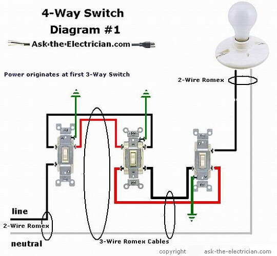
4 way switch install (3 switches total in this case)

There are 3 switch boxes, some switch boxes co-exist with switches with other circuits, and one switch box has ONLY this 4-way configuration in it. All boxes have neutral bundles (ONE of the boxes - one with three separate switches - has two neutral bundles, not tied together?)

At any rate, I have tried with no success to get my 4 way configuration working as intended. I am using one primary and two aux switches. No matter what I do I can only get to 80%~ brightness and it stops there. If I try it from an AUX switch, however, the lights will go to full bright momentarily while the aux switch is being HELD down. Once released the lights drop back down. I have tried converting this to a standard 3 way circuit (by wire-nutting together the items in the “middle” box - the switch that exists by itself) and that still results in the same thing, 80% brightness. Now, the part I cannot figure out is, if I even DISCONNECT the traveller at the master switch it immediately starts working at 100% brightness (obviously disabling slaves). I cannot figure out why. I have also tried leaving the traveller CONNECTED at the Master switch but capping it off at the slave switch, and it results in the same 80% brightness issue. Does anyone have any insight as to why this would be happening? I have struggled with this one for about 4 hours last night, up and down three flights of stairs, and am about to throw the towel in… any recommendations are greatly appreciated. Thanks in advance.

PS, I found a wiring diagram which seemingly represents my configuration:

Again, any help would be GREATLY appreciated. Thanks!

Go in steps. First make it work with just your primary switch. Then add an auxiliary switch. Test again. Then add another. Test again.

Sounds like it appears to work when you disconnect the traveller at the primary, but not when you disconnect it at the auxiliary (and not using a second auxiliary). That seems to indicate they’re not the same wire.

The primary switch needs to be connected to permanent power (so the Z-Wave radio is always powered) and control the load. This does not match the diagram you are referring to.

Are you sure it is a 4-way, and not a 5-way (or more). 3 flights of stairs could indicate 5-way.

@tbever

I’m glad that the CA600 worked out for you, they came in handy for me too. I spent countless hours trying to get the GE/Jasco 3-Way switch kits to function properly before I realized how the GE 3-Ways are actually designed and meant to be wired and I knew then that they wouldn’t work with a traditional 3 Way circuit. At least with the CA600 I could get it working as I needed to use both travelers and not just one. My 3 Way circuits are wired in my home like option 3 within the link below.

[quote=“iflym3, post:81, topic:167413”]The Main switch functions like a normal 3 Way switch should, however the secondary or auxiliary switch functions more like an on/off switch. Both require neutral and the main traveler (one traveler and not 2 like normal 3 way circuits have) has to be connected directly to the auxiliary switch in order for these kits to work properly.

If anyone needs help with 3 Way Circuits, please check out the below link…

[url=http://www.homeimprovementweb.com/information/how-to/three-way-switch.htm]http://www.homeimprovementweb.com/information/how-to/three-way-switch.htm[/url][/quote]

You kinda have to match your existing wiring with the switches that you plan to buy (I learned a hard lesson on this one), sry I did forget to mention that the CA600’s do come with the air gap switch in the off position.

Option 3 can be made to work with the GE kit, but you’d have to change things around behind the light as well; not just in the 2 switch boxes.