I ordered a Fibaro Dimmer 2 and Bypass device for my upstairs landing / hallway lights.
I have 2 light switches one at the bottom of the stairs and another one upstairs on the landing.
I have no neutral wires in the house behind the light switches. This is UK wiring in a 70s house.
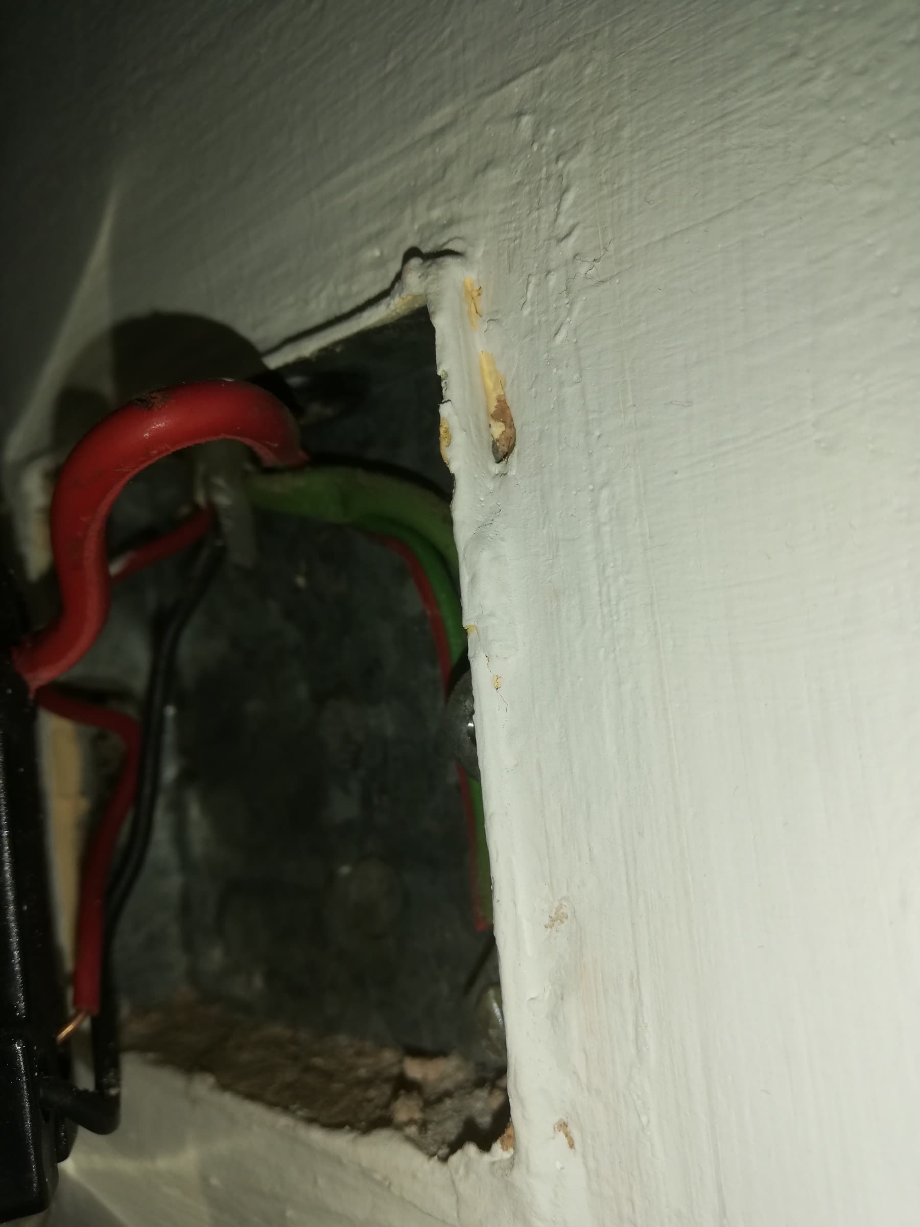
These are photos of the light switch downstairs.
There is a red and black cable at the bottom of the switch and a red cable at the top of it. There is also a red / green cable and a green cable going to an earthing point on the metal back box.
This is the upstairs light switch and I think it is this one that is wired to the ceiling light?
The wiring looks the same at the other switch, there is a red and black cable at the bottom of the switch and a red cable at the top of it. There is also a red / green cable and a green cable going to an earthing point on the metal back box.
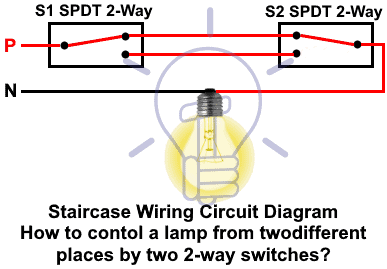
I have wired in lots of Dimmer 2 modules before but never when there was a 2-Way light switches setup.
Red and green cables look like the Pre-1977 IEE colour coding. But then protective earth (green) and phase (red) would cause a short circuit
Could be a mix of different decades. The red and green cables that are clamped together seems to be protective earth as they are clamped to the metal housing. You can only measure the rest to be sure.
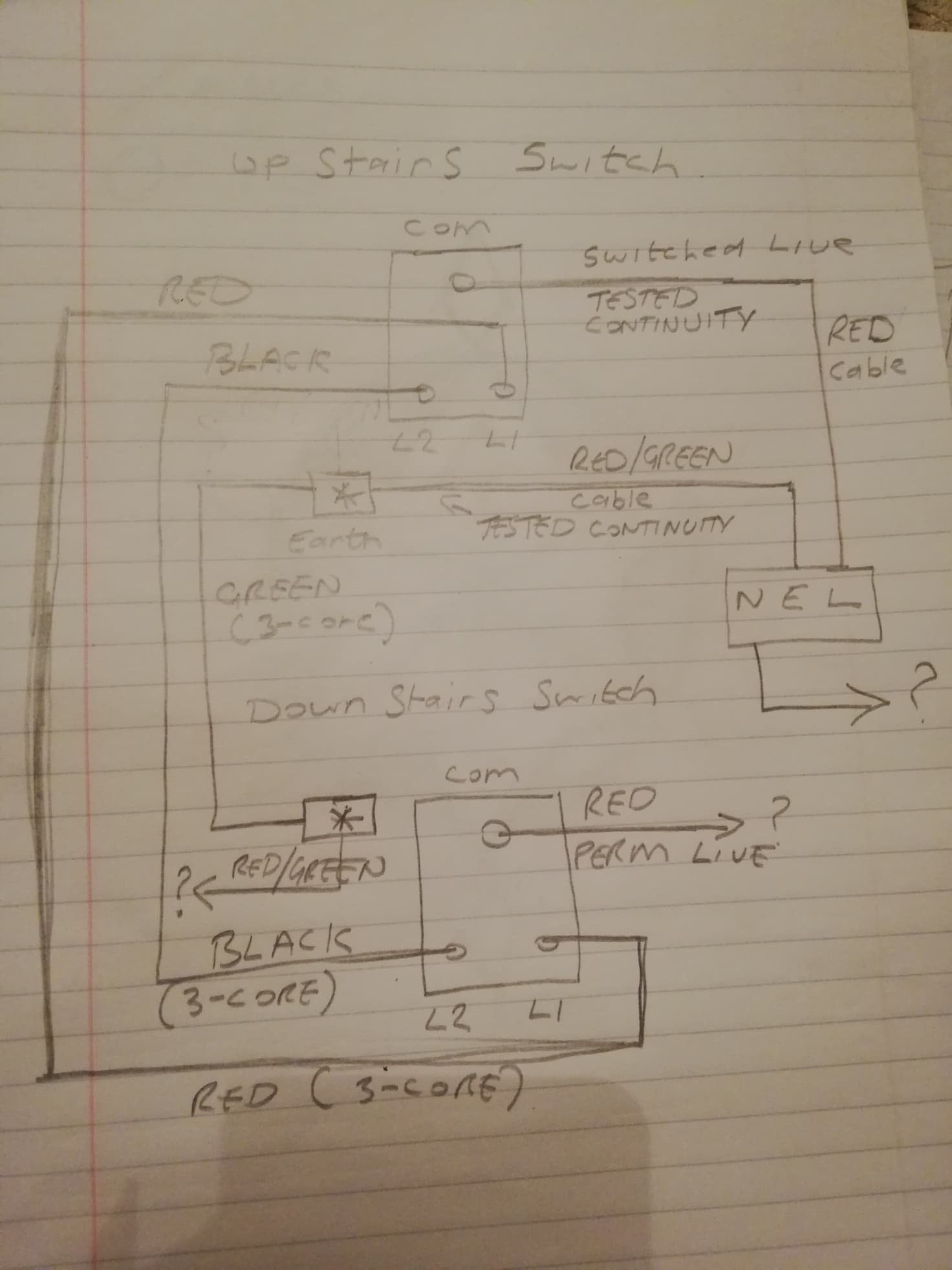
That diagram I drew yesterday is actually correct, which is surprising as I guessed half of it.
Anyway using a long cable from upstairs to downstairs I have just bellled out all the wires with the multi meter for continuity.
I drew the diagram again which is below.
There is no permanent Live at the upstairs switch it seems, after testing with an electricians screw driver that lights up.
Which I think might be a problem, as I think the Fibaro Dimmer 2 module needs to be installed in a position that has permanent live and also the wires going up to the light bulb.
Any suggestions? Someone must have done this with similar 70s style house wiring.
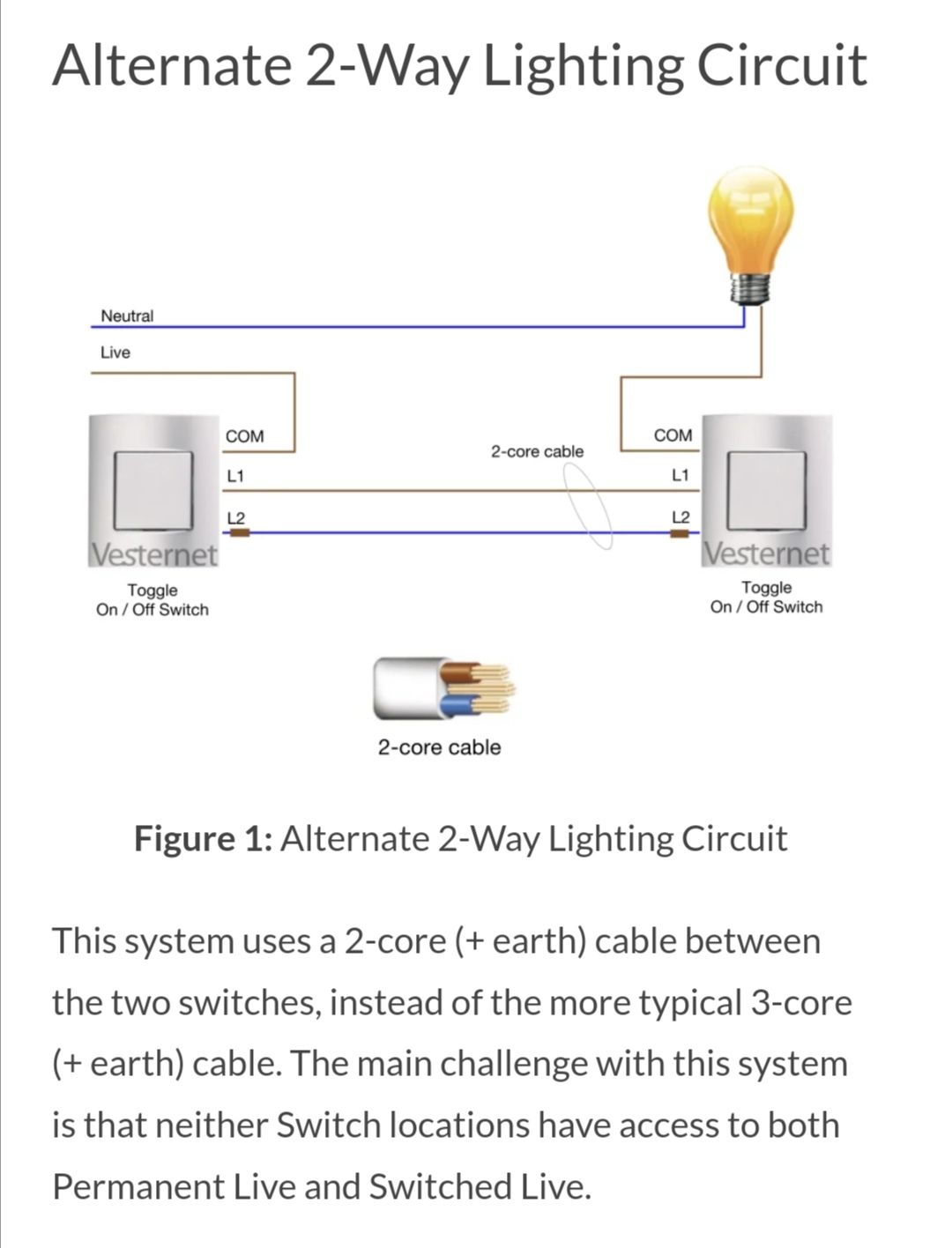
OK I’ve read that article again and I don’t like any of the options, as it requires adding a new wire between the switches which isn’t going to be possible or re-wiring the live to the other upstairs switch also probably not possible.
Or maybe using two Dimmer 2 modules one for each switch as show in the last example on the article, which is more cost.
Or I do a hack? There is a 3 pin plug socket directly below the upstairs wall light switch. Wonder if I could pinch a perm live feed from that to power the Dimmer 2 and install it behind the upstairs wall light switch.
So I am wondering if I can cheat and if this would be safe to do so?
This is from the user guide for:-
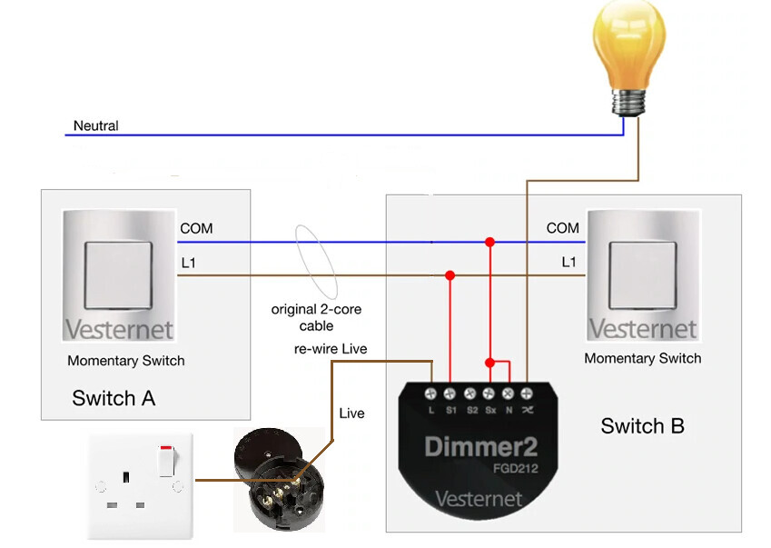
Momentary Switches - re-wire Live to Switch B
I am wondering if I can do this instead, pinching a perm live from the plug socket to feed the Fibaro module and using a junction box or some kind of inline fused spur etc.
EDIT: DO NOT DO THIS BAD IDEA
The original perm Live located at switch A would be not then used and terminated.
Or thinking about it, the ceiling pull cord switch for the bathroom lights is just the other side of the same stud partition wall where the upstairs landing light wall switch is.
Maybe I can just pinch a permanent live from that and drop it down inside the wall to where the wall light switch is.
Not sure yet if it would work, but you have to make sure that neutral and live are coming from the same fuse. Are you sure this is the case for what your trying to do?
Hi CW,
Your Leccy mate is right, mixing circuits is not a good idea. The lighting would be on a power circuit, probably 30A, instead of typically 5A for a lighting circuit.
Does not sound like you have RCDs, but mixing would cause problems in future if you upgrade the Consumer Unit. (I put separate MCBOs on my consumer unit, and the landing light tripped the circuits every time. I found that the Downstairs switch was taking Live from the Downstairs circuit, but the light was using Neutral from the Upstairs circuit. So turning on the light meant that the there were different Live and Neutral currents in each circuit and the so MCBOs would trip).
Repurposing the wires as in your post should be fine, your Live lighting would all be off the Light MCB, and you probably have a single common Neutral bar.
Octoplayer (not a qualified Electrician, but Fellow of Inst of Physics)
Success, I’ve actually done the wiring today rather than just thinking about it
I am still currently using the original bog standard UK toggle / latching light switches, I may change to 3 position retractive / momentary switches later for dimming and double click scene activations etc.
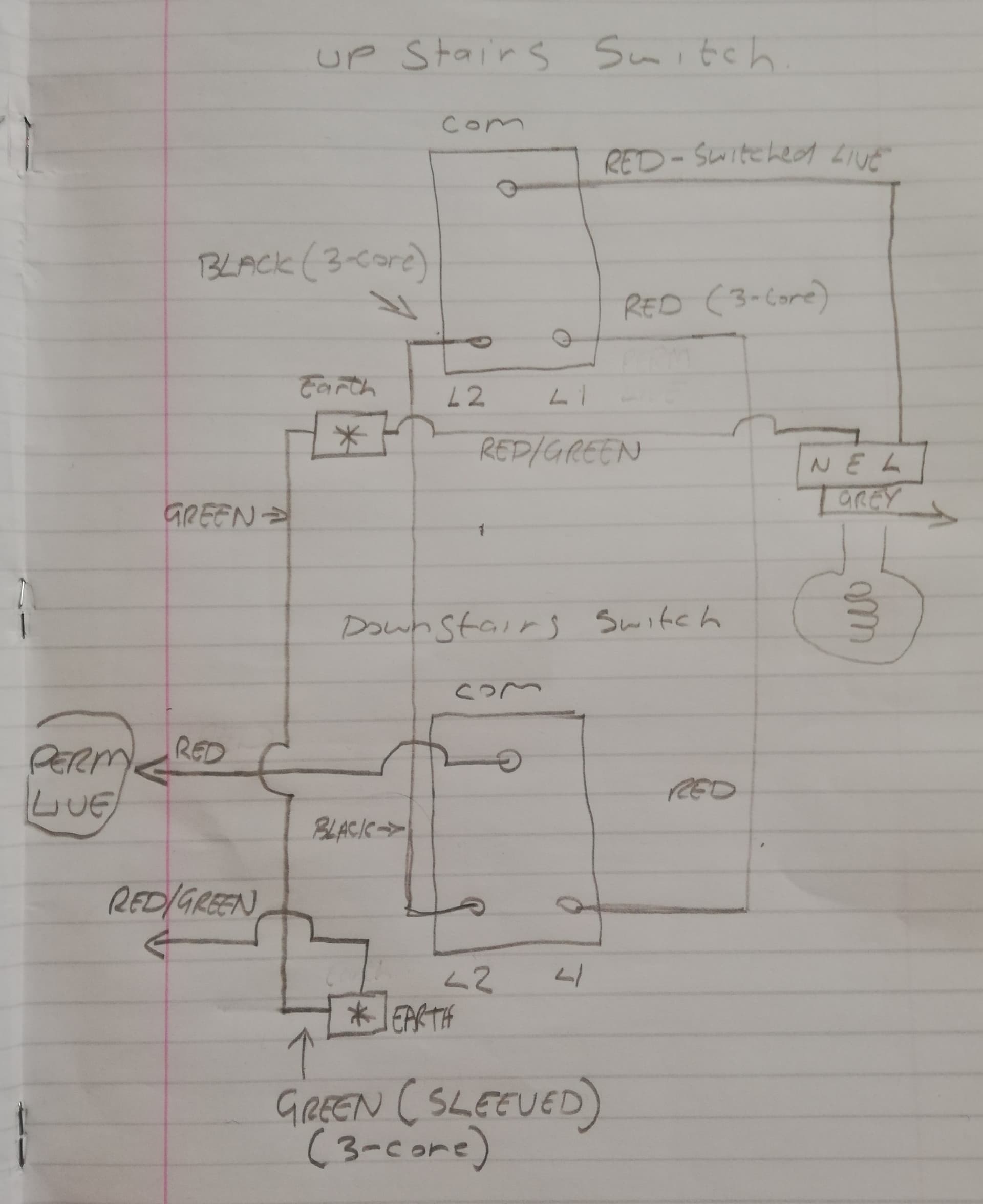
So I followed this diagram instead today.
Toggle Switches - rewire Live to Switch B
The following parameters need to be set:
20 - 1 - enables the dimmer to work with a toggle switch (default is 0 for a momentary switch)
26 - 1 - enables the dimmers S2 switch to also control the dimmer (default 0)
The upstairs light switch only started working again after setting parameter 26.
Now both light switches work to turn on / off the light.
I also had to force a calibration for the bypass device as before I did this, the lights would turn on and then turn themselves off again. That is done using parameter 13.
So pretty happy its working now, as without pinching that perm live from the junction box above the bathroom ceiling from the lighting ring there, this would not have been possible without running an extra new wire between the two switches.
My sparky friend did say “Taking it from a lighting circuit is fine”.
As it was I could just drop down a new short wire from the bathroom ceiling in the loft down the stud partition wall to the upstairs hallway light switch for the new perm Live to run the Fibaro Dimmer 2 module.
Best Home Automation shopping experience. Shop at Ezlo!