A DIY General Purpose WiFi (IP) Based IO Module for Ezlo

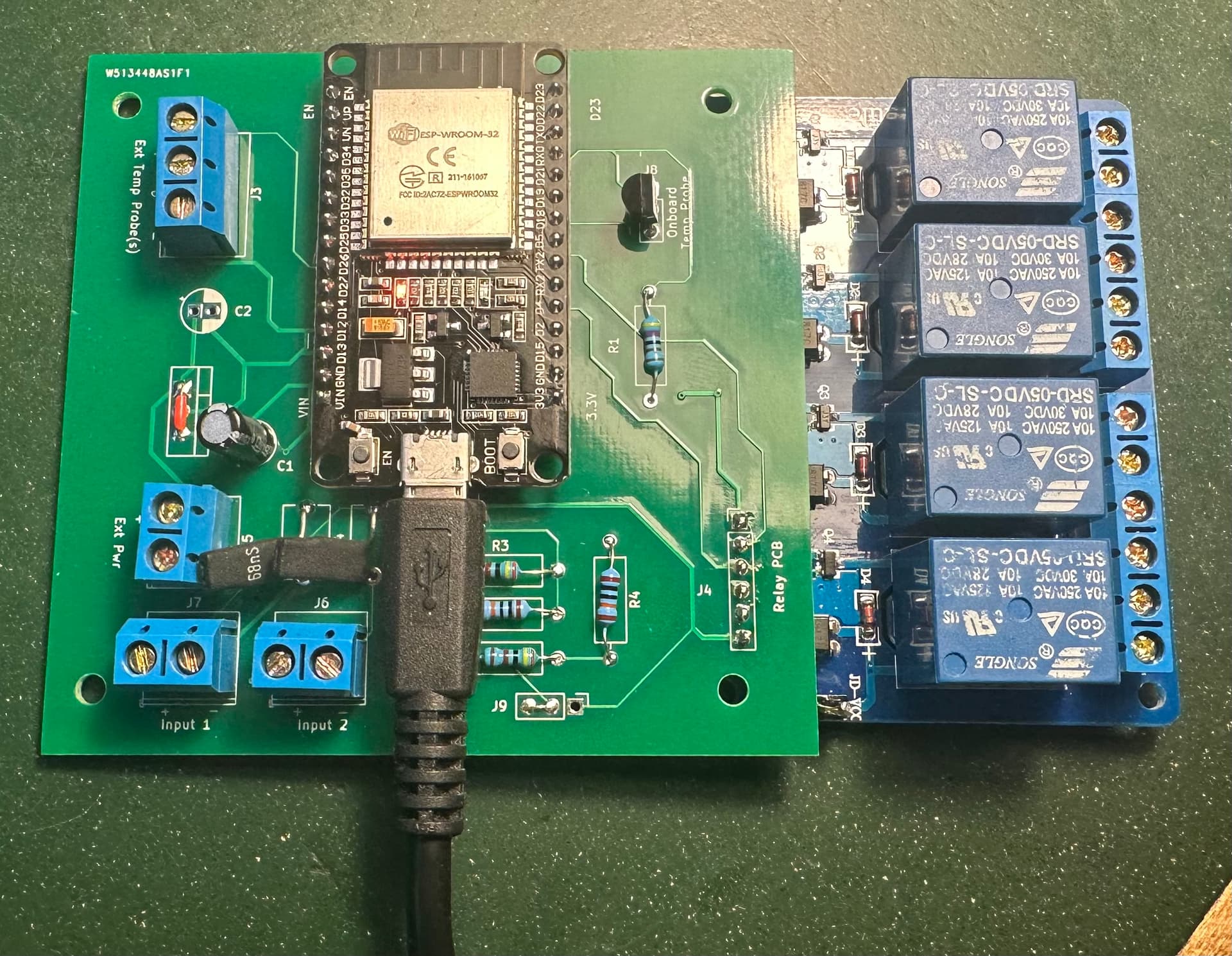
I have developed an ESP32 based general purpose IO module that controls a bank of 4 relays, reads up to 10 DS18B20 temperature probes, and has two switch to ground inputs.

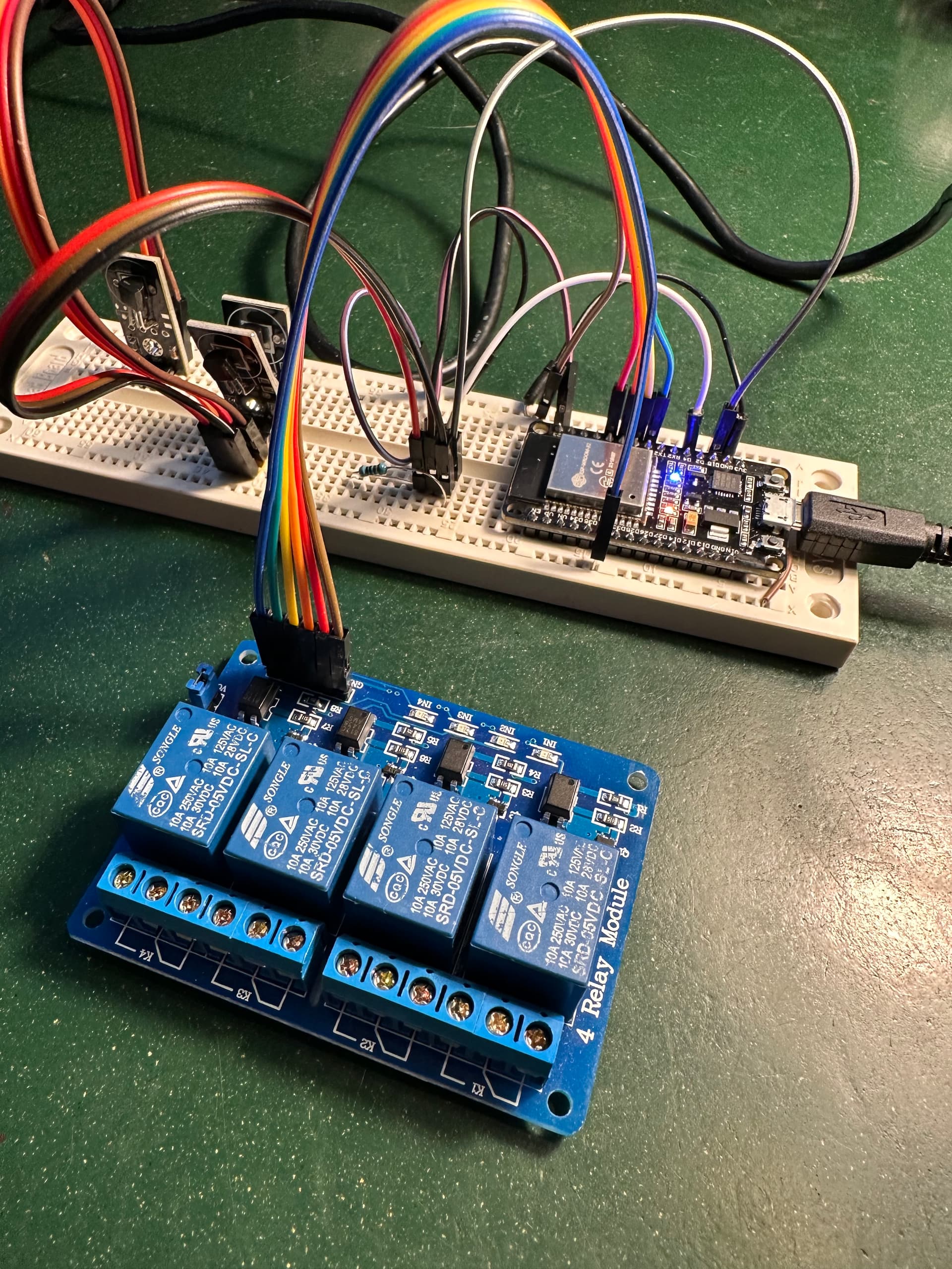
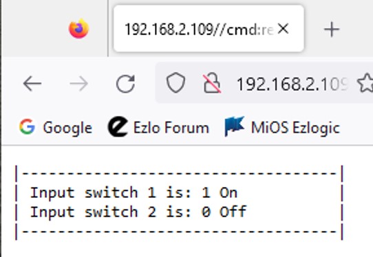
The module seems to work fine and can be queried or controlled from a web page http query on my LAN.

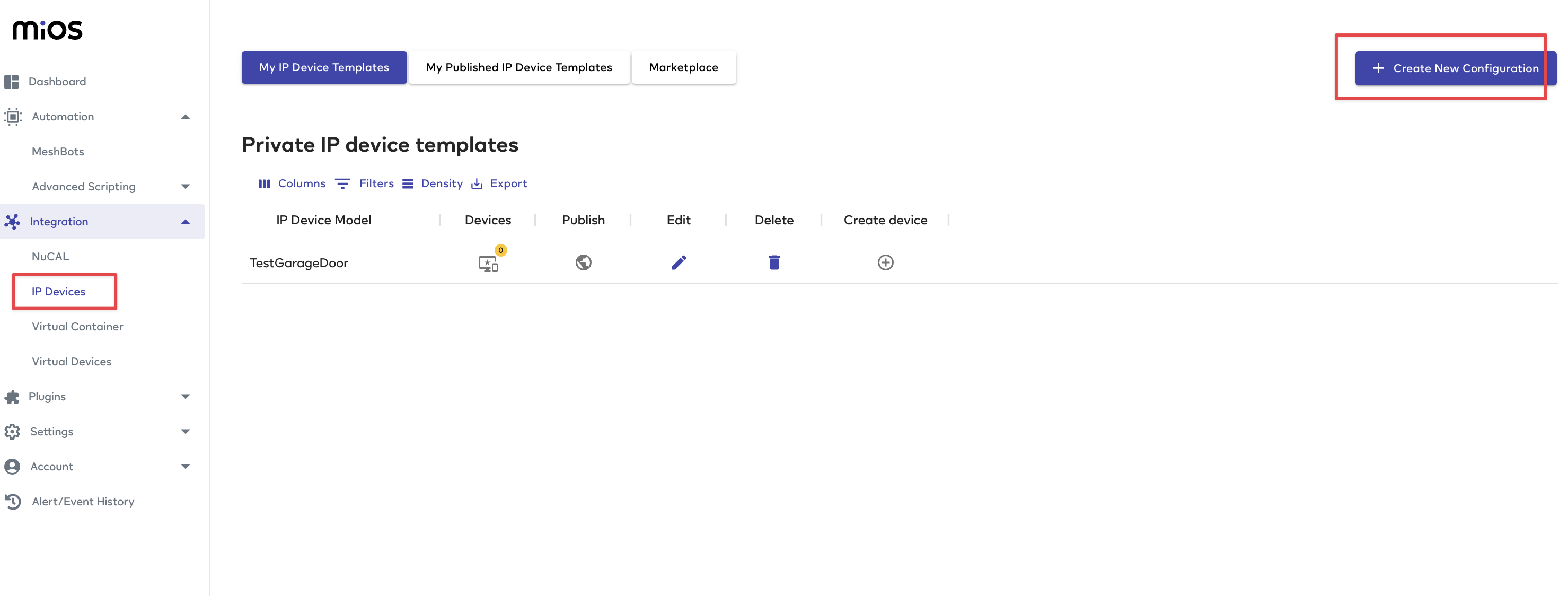
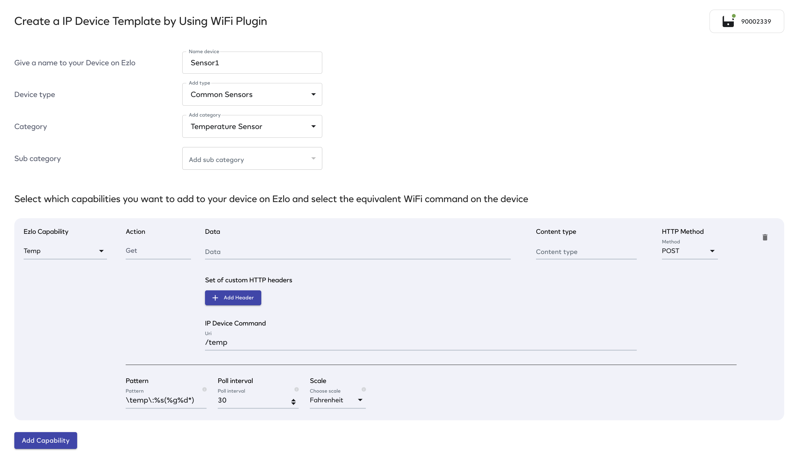
I have created a number of meshbots (http: GET) on my EzloPlus to control the various output devices on this IO module. I can manually run any of these meshbots and the desired state is set on the IO module. So now I can create other meshbots that control devices on my EzloPlus and devices on the IO module. I just have to think of meshbots for the IO module being the equivalent to devices on EzloPlus.

So far so good.

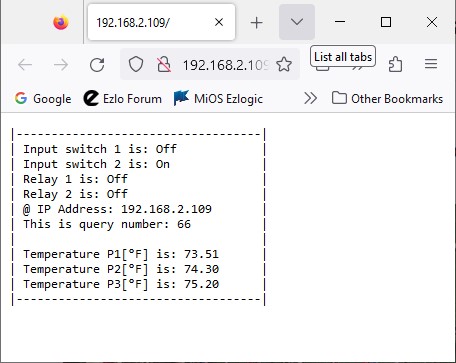
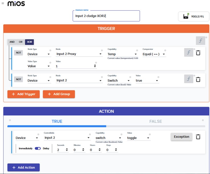
Now I want to be able to read the temperature probes and the input switches and put them into float and boolean variables in EzloPlus. I have created meshbots which query the IO module and stuff the response string into a string variable. So I know the query and accepting the text response is working fine (see screenshot attached).

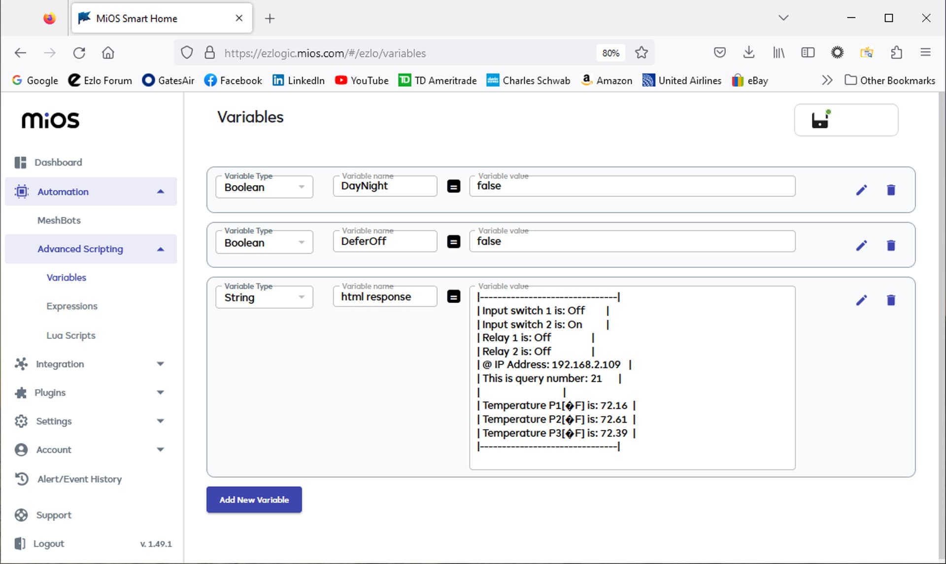
Now I want parse the returned string and use this to set new float and boolean variables which will be later used downstream in other meshbots.

So my question is this. What is the best way to parse a string variable and in turn set 4 boolean variables and several float variables? I want to do this locally on EzloPlus and not go out to a web service for this. I’m not a professional software developer so any help is welcome.

p.s. for now I am happy to poll the IO module to get the various state and temp information. Eventually I’d like to get to the point that a switch closure at the IO module gets immediately updated in the variable on EzloPlus. I need to walk before I run though, so just polling is fine for now.

3 Likes

Hi @curiousB ,

Since you only use switch, relay and sensors, why don’t you give a try to IP device generator plugin ?

Go the Integration → IP Device plugin

There create a configuration for each of your sensor, relay or switch separately

I will get you more detail on this if needed

That hadn’t occurred to me. I’ll give it a try. Thanks.

OK some updates here. So far I have been able to create devices for each of the four relays in my general purpose IO Module mentioned a couple posts back in this thread.

I can create a device for each relay and they populate in the iPhone Vera app and show up on EZlogic dashboard. Easy to do and worked without much drama. Turn off and on works perfectly no issues. No lag or delays to speak of. The switch device type would benefit from a polling capability as well though. It presumes state of the relay by the last command issued. If I put a local switching capability on the IO Module that changes the relay state there is no mechanism to report that back to EzloPlus. Since local switching is a common capability the switch function should probably be expanded to include a periodic poll of the device, a sort of audit if you will, to confirm the device state matches what EzloPlus thinks the state is. Even better would be like in ZWave with the instant capability where a local state change automatically sends the info back to the controller so it gets updated there. For now it works fine reporting back or polling can be on the todo list.

I then created IP Device template and child device(s) for the temperature probes off of the IO module. I can support up to ten DS18B20 3-wire temp probes on the IO module. This was a little more difficult but eventually worked out. I had to modify the HTTP Get response coming from the IO module to eliminate a few special characters (I had [ and ] and | in the response) and that seemed to bother the matching function in the IP Device template Pattern matching. I also had to modify the IO module to always report three digit temperatures even if the first two digits were zeros and it puts a + or a - before the reading (ie -003.23 or +123.21 or -015.12) . So I wasted a lot of time figuring out the Pattern match so here goes so others don’t fall down the same rabbit hole I got lost in for a couple days.

The pattern I used in the end is: Probe Number 2 in F is: (%s%g%d%d%d.%d%d)

The pattern matching needs to see this entire string (i.e. Probe Number 2 in F is: +071.12) but then passes only the part in parenthesis upwards for the temperature reading. Seems simple now but the parenthesis are important and not having special characters ( ( ) . % + - * ? [ ^ $) in the text matching string before is also important. Also the digits have to match the number of %d in the pattern. When I had %d%d.%d%d and temp rose above 100 degrees it lost the most significant digit. similarly if temp was 5.24 degrees it didn’t match %d%d.%d%d and wouldn’t be reported. So you have to have some precision here as it turns out. I suppose LUA and programming experts might be able use these code in a more flexible manner but this was where I got. Anyway hopefully this helps you avoid a lot of wasted time on parsing responses for queries. Here is a key to the digit codes:

  • .: (a dot) represents all characters.
  • %a: represents all letters.
  • %c: represents all control characters.
  • %d: represents all digits.
  • %g: represents all printable characters except space.
  • %l: represents all lowercase letters.
  • %p: represents all punctuation characters.
  • %s: represents all space characters.
  • %u: represents all uppercase letters.
  • %w: represents all alphanumeric characters.
  • %x: represents all hexadecimal digits.

My last functionality in my IO module is two contact closure to ground inputs. I was thinking much like the Temp probes it would be some sort of polling capability to go read the state of the switches every few minutes or seconds depending on the importance of the contact closure. As I wade in on creating this IP Device template I couldn’t find a suitable “Ezlo Capability” for a contact closure. The list had CO2 level, CO Level, Current, Dimmer, Humidty, Lux, Power, … and even switch. Unfortunately the switch presumes a switch output, something to be controlled as opposed to an switch like a door or window reed switch which needs to be polled. The device type and categories seem to presume simple input devices but the Ezlo Capability once you start building the template is missing this simple polled device type.

So that is my ask, is there a profile (or could there be one added) to allow the reading of a contact closure and storing that in a device state or a virtual device state. Once there that device can be used as a trigger for other actions and meshbots. I can live with polling only for now and maybe down the road something like “instant status” could be added.

poll screenshot

1 Like

so 2 requests for us :

  • Add polling for switch capability
  • Add d/w , and motion sensor capabilities, you can use d/w for contact closure

Created tickets for you : Service Desk Service Desk

Yes those would be great. I have other findings I’ll send along when I get some time to collect my thoughts.

I did find a work around for the absence of a bool (binary) input capability (door window dry contact closure to ground). Its very unconventional but works.

Step 1. I modified the output of my IO module to respond to a switch query as thus:

Switch output

Step 2. I created a temperature IP Device and used this pattern to capture the 1 digit output:
Starting with the I in Input >> Input switch 1 is:(%s%d)
This is received as a float (I think because it is for my real temp probes) so now I have a temperature reading of 1 degree or zero degrees.

Step 3. I created a virtual switch called Input 1.

Step 4. I created two meshbots to trigger on the temperature reading. If the temp == 1 then I turn on the virtual switch, if the temp == 0 then I turn off the virtual switch.

Step 4 gets the float back to a boolean/binary on/off and is then usable in downstream meshbots.

I tested this and it works fine. A round about way to get a binary output from an IP Device when you are missing certain input read capabilities. There is a slight lag from the temp change until the virtual switch toggles but there is a lag anyway due to the polling nature of the reading. The one catch is if you directly change the state of the virtual switch that doesn’t do anything because its an input. So you have to be mindful of trying to send state changes that can’t be made.

Anyway a band-aide for someone in a pinch to input a binary value when the functionality isn’t there yet.

I grouped all the devices related to the IO Module to a room called IO module. Here is the dashboard for that group of devices:

So I have a device that is quite flexible in its application and very inexpensive, under $20 in components.

Garage Door 1 and 2 are the other two relays. The twist here is that my IO Module only turns them on for 700ms to simulate pressing a button. This way it wires directly to the LV switch for the garage door. The 700ms is configurable in the IO Module but that seems the right amount. I also created a recover meshbot for these two devices. Turning them on in EzloPlus turns on the relays but the IO module turns them, off after the delay. So this is where a switch polling might be nice. As another band-aide I created a meshbot that triggers on either garage door being turned on then 3 seconds later it switches the device back to off. Switching to off doesn’t do anything as I didn’t even populate the command string for the Garage door off switch option. But it does return the switch to off on the dashboard to match what the IO Module has done on its own.

I’ll write up more of a how to guide later but thought I would share these findings. I have implemented 100% of the functionality I set out to do. I am not a professional software developer so maybe this will encourage others with interest to give it a go.

2 Likes

Excellent news! Thank you for sharing.

I refined my approach on step 4 above. Instead of two meshbots (one for on and one for off) to set the virtual switch to match the state from the temp probe (proxy to a binary input) I collapsed it into one using the XOR function. Reduced some meshbot clutter by doing it in one.

The logic here is if the proxy doesn’t match the virtual switch then toggle the virtual switch such that they match. This way asynchronous changes to the proxy (i.e. real input changes at the ESP32 input) are replicated on the virtual switch boolean function. The 2 second delay is just to eliminate an updating race condition between EzloPlus and the iPhone client.

The bonus is if someone switches the virtual switch at the iPhone client or in the dashboard this meshbot will trigger a mismatch between those and restore them to match so I solve the problem of ambiguity between the client state and the actual input due to inadvertent toggling of a virtual switch in a GUI.

2 Likes

Did a transition PCB from ESP32 to relay board to move away from a breadboard.

Features:

  • One onboard DS18B20 temp probe
  • Screw Terminal for up to 9 additional DS18B20 probes
  • Screw Terminal for two switch closures to ground (garage door open/closed switches). Extra protection to ESP32 inputs.
  • Screw terminal for external power in ( I will probably just power via the USB.
  • four relays capable of up to 10A @ 240VAC
  • two relays configured as garage door open/close (pulsed output)
  • two relays as general purpose on/off. Garage lights?

3 Likes

As I progress on my multi-function device I wonder of there is a way to do the following:

  • Create an IP Device template.
  • Allow the capability section to have multiple string matches and stuff the results for each match into a variable.
  • What would be the meshbot or LUA command to use one of these variables to overwrite the state of a device in EzloPlus (i.e. the GUI says “off” but the polling says “on”)? I suppose I could just have a meshbot action (XOR device state with Poll result) to change the state of the device which would change the GUI and send a change command but that would be ignored by the device because it already is at that state. If I wanted a more elegant scheme to over-write the variable state as shown in the GUI how would I do that? By doing this I can create a polling scheme to check state of the device(s), compare to what Ezlo thinks it is and correct for a difference. In effect the audit loop I have mentioned before. I suspect this might be doable with native functionality already in place.
  • By allowing this I can do one poll to get the status of all the inputs and outputs in one poll. Today’s one response to one poll limitation means a lot of polling traffic that could be simplified.
  • Maybe this is doable already, key is the multi response poll into separate variables. Is there a way to do that already?

Matching Pattern(s) // allow system to parse multiple string matches into variables in one poll

variableFloat1 = Probe Number 1 in F is:(%s%g%d%d%d.%d%d)

variableFloat2 = Probe Number 2 in F is:(%s%g%d%d%d.%d%d)

variableInt1 = Input 1 is:(%s%d)

variableInt2 = Input 2 is:(%s%d)

variableInt3 = Output 1 is:(%s%d)

variableInt4 = Output 2 is:(%s%d)

variableInt5 = Output 3 is:(%s%d)

variableInt6 = Output 4 is:(%s%d)

Hi @curiousB we already noted down all your previous requests. Let us proceed on them one by one. We started to add polling for power capability. Then we will do in this order:

  • modify template parameters via device settings
  • stop polling after the device is not reachable for some time. Later I want to restart polling / or check manually if the device is reachable
  • use door/window and motion sensors capability in sensor device types.
  • test HTTP requests while creating the template and see the response on the page directly.
  • set MQTT topics instead of HTTP URIs to send device commands, get data via mqtt messages ( this can be done in parallel if we can)

after those we will start working on multiple device capability.

1 Like


Picked up a handful of ESP32 minis and hermetically sealed DS18B20 temp probes $9.51 for the both. Added an old USB charger and a cord and I have a WiFi based temp probe. Just loaded my IO Module Arduino code on the ESP32 but only the temp probe portion is getting any usage. The probe with a cord is needed because the ESP32 has a heat profile that throws off the temp reading if the sensor is within 10" (250mm) of the ESP32.

It is polled by Ezlo Plus from an IP Device template. Works flawlessly. I like having an IP Device rather than a peer EzloPi given my preference for the controller (Ezlo Plus) to be the master and the device the slave.

2 Likes

I did something similar recently using a LUA script that was written for me by one of the devs. I wrote about it here.

But seems you managed to do this using the IP Device Generator plugin instead ?

Did you design that PCB yourself and then have it made?

Yes. I designed it on KiCad then sent the Gerber files to PCBWay.com. I had the board blanks to me in a week. Its very inexpensive as well. KiCAD is easy to use, I was proficient enough in just a few hours of usage. Mind you I wasn’t doing a 16 layer design… I was a fun project to try to do something concept to implementation. Just waiting on some more capabilities in the IP Template capability of Ezlo to take this to completion.

As noted in the picture I mounted the ESP board as a daughter board to my IO board. I guess a purist would have put my IO board and the ESP32 SMT components onto a single board but I was just looking for a cleaner way to interconnect everything. This way I had no high speed traces, ground planes, and noise shielding complexities in my IO board which simplified the design.

1 Like